Table of Contents
Advertisement
Quick Links
Fix-EZ
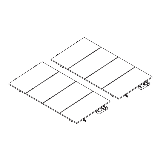
Designed for flat roof applications, the multifunction Fix-EZ solar mounting system mounts solar photovoltaic (PV) modules on
roof tops with minimal load and materials, thereby reducing installation time and costs. The Fix-EZ is specifically designed to meet
or exceed applicable IBC, ASCE, and UL standards.
Features
•
Conforms to UL 2703
•
Certified to ULC/ORD Std C1703
•
Fire class resistance rating: Class A when used with
Type I or Type II photovoltaic modules in landscape orientation only
•
Multiple module tilt options available
•
Portrait or landscape module orientation
•
Ballast block included
Includes Rapid5K
•
TM
•
Wind tunnel tested
•
Optional wire management
•
30 Amp fuse series rating
Provided as a complete mounting system, the Fix-EZ includes several multifunction components to maximize functionality and
minimize cost. Ballast blocks act as ballast weight as well as system support. Module mounting rails support modules⁵ and act as
windbreak with Rapid5K™ module clamps securely holding modules in place while bonding/grounding them to the system. The
following is a guide to properly install a Fix-EZ in order to meet design and test standards.
Key Components
7
1.
Concrete ballast blocks
2.
Adjustable L-foot
3.
Module support rails (purlins)
4.
Rapid5K
grounding module clamps
TM
1
The Fix-EZ is evaluated for electrical bonding only. The Fix-EZ meets all IBC and ASCE requirements for structural loading; it was not evaluated for loading under UL 2703.
2
Special consideration needs to be taken during design phase if system requires protective fire barrier.
3
Module tilt will vary depending on module manufacturer's connection requirements: tilt options range from 7 degrees to 15 degrees
4
Maximum number of modules shall not exceed maximum system voltage.
5
This racking system may be used to ground and/or mount a PV module complying with UL1703 only when the specific module has been evaluated for grounding and/or mounting in
compliance with the included manual
6
Installer is responsible for verifying that photovoltaic system meets applicable NEC standards.
Individual parts and components may vary from system-to-system. Please reference system specific drawings.
7
© Schletter Canada Inc. • 3181 Devon Drive • Windsor, Ontario N8X 4L3 • Tel: (519) 946 – 3800 • Fax: (519) 946 – 3805
E-mail: mail@schletter.ca • www.schletter.ca
Fix-EZ™ Installation Manual
1
3
4
grounding module clamps
1
2
2
3
6
4
3
1/12
MI-018CA
072216
Advertisement
Table of Contents

Related Manuals for Schletter Fix-EZ


Summary of Contents for Schletter Fix-EZ
- Page 1 The Fix-EZ is evaluated for electrical bonding only. The Fix-EZ meets all IBC and ASCE requirements for structural loading; it was not evaluated for loading under UL 2703. Special consideration needs to be taken during design phase if system requires protective fire barrier.
- Page 2 2/12 © Schletter Canada Inc. • 3181 Devon Drive • Windsor, Ontario N8X 4L3 • Tel: (519) 946 – 3800 • Fax: (519) 946 – 3805 MI-018CA 072216 E-mail: mail@schletter.ca • www.schletter.ca...
-
Page 3: Installation Tool List
Ratchet and/or rechargeable power drill • Chop saw 3/12 © Schletter Canada Inc. • 3181 Devon Drive • Windsor, Ontario N8X 4L3 • Tel: (519) 946 – 3800 • Fax: (519) 946 – 3805 MI-018CA 072216 E-mail: mail@schletter.ca • www.schletter.ca... - Page 4 Due to the variety of roofing material, protective padding composition will vary based on substrate compatibility. Consult certified roofing contractor for best practices. 4/12 © Schletter Canada Inc. • 3181 Devon Drive • Windsor, Ontario N8X 4L3 • Tel: (519) 946 – 3800 • Fax: (519) 946 – 3805 MI-018CA 072216 E-mail: mail@schletter.ca •...
- Page 5 18 feet on all rear rails. Attach labels to rails using self-drilling screws 5/12 © Schletter Canada Inc. • 3181 Devon Drive • Windsor, Ontario N8X 4L3 • Tel: (519) 946 – 3800 • Fax: (519) 946 – 3805 MI-018CA 072216...
-
Page 6: Optional Accessories
(Part #135003-003) grounding lug by at least 1/4 inch 6/12 © Schletter Canada Inc. • 3181 Devon Drive • Windsor, Ontario N8X 4L3 • Tel: (519) 946 – 3800 • Fax: (519) 946 – 3805 MI-018CA 072216 E-mail: mail@schletter.ca • www.schletter.ca... - Page 7 4. Ground Path Diagram Grounding Module Clamp Frame Purlin 7/12 © Schletter Canada Inc. • 3181 Devon Drive • Windsor, Ontario N8X 4L3 • Tel: (519) 946 – 3800 • Fax: (519) 946 – 3805 MI-018CA 072216 E-mail: mail@schletter.ca • www.schletter.ca...
-
Page 8: Module Mounting
• Use of impact driver is not recommended. 8/12 © Schletter Canada Inc. • 3181 Devon Drive • Windsor, Ontario N8X 4L3 • Tel: (519) 946 – 3800 • Fax: (519) 946 – 3805 MI-018CA 072216 E-mail: mail@schletter.ca • www.schletter.ca... - Page 9 Position modules Secure all connections with module clamps 9/12 © Schletter Canada Inc. • 3181 Devon Drive • Windsor, Ontario N8X 4L3 • Tel: (519) 946 – 3800 • Fax: (519) 946 – 3805 MI-018CA 072216 E-mail: mail@schletter.ca • www.schletter.ca...
-
Page 10: Equipment Grounding
Camcar Corp. division of Textron Industries. ® 10/12 © Schletter Canada Inc. • 3181 Devon Drive • Windsor, Ontario N8X 4L3 • Tel: (519) 946 – 3800 • Fax: (519) 946 – 3805 MI-018CA 072216... -
Page 11: Maintenance
For more information Fix-EZ Product Sheet Installation Video 11/12 © Schletter Canada Inc. • 3181 Devon Drive • Windsor, Ontario N8X 4L3 • Tel: (519) 946 – 3800 • Fax: (519) 946 – 3805 MI-018CA 072216 E-mail: mail@schletter.ca • www.schletter.ca... - Page 12 TSM-PD14 TSM-PD05 TSM-PD05.08 TSM-PD05.05 TSM-PEG5 TSM-PEG5.07 TSM-PEG14 TSM-PEG40.07 12/12 © Schletter Canada Inc. • 3181 Devon Drive • Windsor, Ontario N8X 4L3 • Tel: (519) 946 – 3800 • Fax: (519) 946 – 3805 MI-018CA 072216 E-mail: mail@schletter.ca • www.schletter.ca...
Need help?
Do you have a question about the Fix-EZ and is the answer not in the manual?
Questions and answers