Table of Contents
Advertisement
Quick Links
RETURN TO MAIN MENU
IM659-B
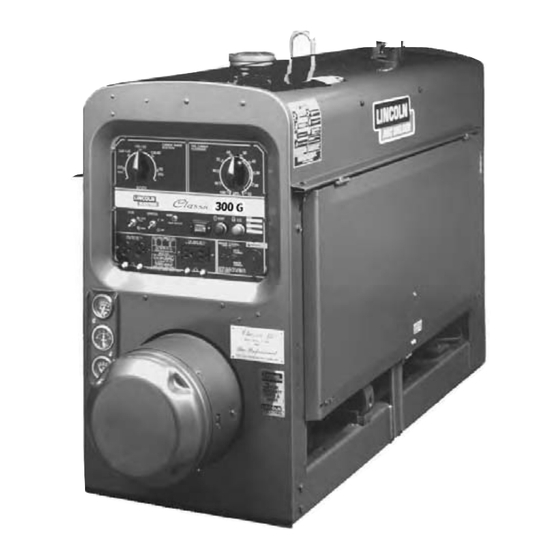
CLASSIC
300G
®
December, 2004
For Machines with Code Numbers 10659,10912,11135
Safety Depends on You
Lincoln arc welding equipment
is designed and built with safety
in mind. However, your overall
safety can be increased by
proper installation ... and
thoughtful operation on your
part. DO NOT INSTALL,
OPERATE OR REPAIR THIS
EQUIPMENT
WITHOUT
READING THIS MANUAL AND
THE SAFETY PRECAUTIONS
CONTAINED THROUGHOUT.
And, most importantly, think
before you act and be careful.
NRTL/C
R
OPERATOR'S MANUAL
Copyright © 2004 Lincoln Global Inc.
• World's Leader in Welding and Cutting Products •
• Sales and Service through Subsidiaries and Distributors Worldwide •
Cleveland, Ohio 44117-1199 U.S.A. TEL: 216.481.8100 FAX: 216.486.1751 WEB SITE: www.lincolnelectric.com
Advertisement
Table of Contents
Troubleshooting

Subscribe to Our Youtube Channel
Related Manuals for Lincoln Electric CLASSIC 300G 10659


Summary of Contents for Lincoln Electric CLASSIC 300G 10659
- Page 1 RETURN TO MAIN MENU IM659-B CLASSIC 300G ® December, 2004 For Machines with Code Numbers 10659,10912,11135 Safety Depends on You Lincoln arc welding equipment is designed and built with safety in mind. However, your overall safety can be increased by proper installation ...
-
Page 2: California Proposition 65 Warnings
351040, Miami, Florida 33135 or CSA Standard W117.2-1974. A Free copy of “Arc Welding Safety” booklet E205 is available from the Lincoln Electric Company, 22801 St. Clair Avenue, Cleveland, Ohio 44117-1199. BE SURE THAT ALL INSTALLATION, OPERATION, MAINTENANCE AND REPAIR PROCEDURES ARE PERFORMED ONLY BY QUALIFIED INDIVIDUALS. -
Page 3: Electric Shock Can Kill
ELECTRIC SHOCK can kill. 3.a. The electrode and work (or ground) circuits are electrically “hot” when the welder is on. Do not touch these “hot” parts with your bare skin or wet clothing. Wear dry, hole-free gloves to insulate hands. - Page 4 WELDING SPARKS can cause fire or explosion. 6.a. Remove fire hazards from the welding area. If this is not possible, cover them to prevent the welding sparks from starting a fire. Remember that welding sparks and hot materials from welding can easily go through small cracks and openings to adjacent areas.
- Page 5 PRÉCAUTIONS DE SÛRETÉ Pour votre propre protection lire et observer toutes les instructions et les précautions de sûreté specifiques qui parraissent dans ce manuel aussi bien que les précautions de sûreté générales suiv- antes: Sûreté Pour Soudage A L’Arc 1. Protegez-vous contre la secousse électrique: a.
- Page 6 The code number is especially important when identifying the correct replacement parts. - Register your machine with Lincoln Electric either via fax or over the Internet. • For faxing: Complete the form on the back of the warranty statement included in the literature packet accompanying this machine and fax the form per the instructions printed on it.
-
Page 7: Table Of Contents
Battery Charging ...A-4 Operation ...Section B General Description ...B-1 Design Features ...B-1 Starting The GM 3.0L Engine...B-2 Stopping the engine ...B-2 Welder Operation...B-2 Duty Cycle...B-2 Control of Welding Current...B-3 Idler Operation ...B-3 Auxiliary Power ...B-3 Throttle Body Deicing...B-3 Accessories ...Section C Optional Equipment (Field Installed) ...C-1... -
Page 8: Installation
Cast Iron Cylinder (K1754-1) Block/Crankcase 53.0 HP @ 1800 RPM DESCRIPTION VOLTS @ RATED AMPS 300 Amp DC Welder All Copper Windings Pure DC Power Generator ENGINE OPERATING LOAD Low Idle (1360 RPM)-No Load High Idle (1800 RPM)-No Load AC Auxiliary-115 Volts-26 Amps... -
Page 9: Safety Precautions
Leaving the doors open changes the designed air flow and may cause overheating. The welder should be located to provide an unrestrict- ed flow of clean, cool air. Also, locate the welder so that engine exhaust fumes are properly vented to an outside area. -
Page 10: Trailers
Consult the engine operation manual for specific engine manufacturer’s recommendations. Upon receipt of the welder, check the engine dipstick to be sure the oil is at the “full” mark. DO NOT overfill. FUEL Fill the fuel tank with the grade of fuel recommended in the Engine Operator’s manual. -
Page 11: Battery Charging
• Connecting a battery charger remove the battery from the welder by disconnecting the negative cable first, then the positive cable and battery clamp. When reinstalling, connect the negative cable last. -
Page 12: Operation
DC TIG welding. This welder is wound with all copper coils, rated at 300 amps/32 Volts, and provides other Classic features such as improved door latches and stainless hinges. With the addition of the optional K623-1 Wire Feed Module ™... -
Page 13: Stopping The Engine
32 arc volts on a 60% duty cycle (consult Specifications in this manual for alternate ratings). Duty cycle is based on a ten minute period; thus, the welder can be loaded at rated output for six minutes out of every ten minute period. CLASSIC 300G... -
Page 14: Control Of Welding Current
IDLER CONTROL OPERATION The idle is controlled by the “Idler” toggle switch on the welder control panel. The switch has two positions as follows: 1. In the “High” position, and the engine goes to high idle speed. -
Page 15: Accessories
30 ft. (9.1m) work cables, headshield, work clamp and electrode holder. WARNING Pipe Thawing with an arc welder can cause fire, explosion, damage to electric wiring or to the arc welder if done improperly. The use of an arc... -
Page 16: Maintenance
----------------------------------------------------------- GENERAL INSTRUCTIONS • Blow out the welder and controls with an air hose at least once every two months. In particularly dirty locations, this cleaning may be necessary once a week. Use low pressure air to avoid driving dirt into the insulation. -
Page 17: Idler Control Maintenance
• Proper operation of the idle control requires good grounding of the TBI controller, and battery. • If desired, the welder can be used without automatic idling by setting the “Idler” switch to the “High” position. -
Page 18: Engine Service Chart
EVERY DAY OR EVERY 8 HOURS FIRST SERVICE - (50 HOURS) EVERY 100 HOURS OR 3 MONTHS EVERY 200 HOURS OR 6 MONTHS EVERY 600 HOURS OR 12 MONTHS Coolant level Conc entration of antifreeze Radiator for contamination or blockage Coolant (NOTE 3) Engine oil level ( NOTE 1 ) Engine oil ( NOTE 1 &... -
Page 19: How To Use Troubleshooting Guide
HOW TO USE TROUBLESHOOTING GUIDE Service and Repair should only be performed by Lincoln Electric Factory Trained Personnel. Unauthorized repairs performed on this equipment may result in danger to the technician and machine operator and will invalidate your factory warranty. For your safety and to avoid Electrical Shock, please observe all safety notes and precautions detailed throughout this manual. -
Page 20: Troubleshooting
PROBLEMS (SYMPTOMS) Machine fails to hold the heat con- stantly. Welder starts but fails to generate current. Welding arc is loud and spatters excessively. If for any reason you do not understand the test procedures or are unable to perform the tests/repairs safely, contact your Local Lincoln Authorized Field Service Facility for technical troubleshooting assistance before you proceed. - Page 21 Arc continuously pops out. FLASHING THE FIELDS: 1. Stop the engine welder and disconnect the positive battery terminal. 2. Remove the cover from the exciter. 3. Turn the “Fine Current Adjustment” (rheostat) to “100” on the dial. 4. Using a 12 volt automotive battery, connect its negative terminal to the negative brushholder. The negative brushholder is the one nearest to the rotor lamination.
-
Page 22: Electronic Idler Troubleshooting Guide
TROUBLESHOOTING ELECTRONIC IDLER CONTROL TROUBLESHOOTING GUIDE Engine Will Not Return to Low Idle in Approximately 10 Seconds After Welding and Auxiliary Loads are Removed Set Idler Control Switch to the Auto Position Check for Continuity through Idler Control Switch Open Closed Remove Molex connector Replace Idler... -
Page 23: Troubleshooting
ELECTRONIC IDLER CONTROL TROUBLESHOOTING GUIDE With Idler Control Switch in the AUTO Position,Engine Will Not Pick Up Speed When: The Arc is Struck Check for loose or disconnected wire running between weld selector switch and output stud. If for any reason you do not understand the test procedures or are unable to perform the tests/repairs safely, contact your Local Lincoln Authorized Field Service Facility for technical troubleshooting assistance before you proceed. - Page 24 Observe all Safety Guidelines detailed throughout this manual PROBLEMS (SYMPTOMS) Engine does not start Irregular running of the Engine. Engine stops running During Operation Engine Protection Light Does Turn On. (Solid Light) If for any reason you do not understand the test procedures or are unable to perform the tests/repairs safely, contact your Local Lincoln Authorized Field Service Facility for technical troubleshooting assistance before you proceed.
- Page 25 Observe all Safety Guidelines detailed throughout this manual PROBLEMS (SYMPTOMS) Engine Stops During Operation and the Engine Protection Light Does Turn On. (Flashing) White or Blue Smoke. Dark Smoke Faulty Charging Starter Motor does not run. Engine Knocking. Lack of Power. If for any reason you do not understand the test procedures or are unable to perform the tests/repairs safely, contact your Local Lincoln Authorized Field Service Facility for technical troubleshooting assistance before you proceed.
- Page 26 Observe all Safety Guidelines detailed throughout this manual PROBLEMS (SYMPTOMS) Surging Large Decrease in Speed. Engine runs Irregularly. Engine fails to pick up speed when Arc is struck. If for any reason you do not understand the test procedures or are unable to perform the tests/repairs safely, contact your Local Lincoln Authorized Field Service Facility for technical troubleshooting assistance before you proceed.
-
Page 27: Diagrams
DIAGRAMS CLASSIC 300G... - Page 28 DIAGRAMS CLASSIC 300G...
- Page 29 K2464-1 REMOTE CONTROL WIRING / CONNECTION DIAGRAM RESISTORS REMOTE CONTROL BOX DIAGRAMS CV "WIRE" CONTROL POT CC "STICK CONTROL BLUE ORANGE CONNECT TO CASE CLASSIC 300G CABLE CONNEC TION TABLE LEAD COLOR ORANGE BLUE WHITE JUMPER WHITE JUMPER S26097...
- Page 30 DIAGRAMS CLASSIC 300G...
- Page 31 ● WARNING ● Spanish ● AVISO DE PRECAUCION ● French ● ATTENTION ● German ● WARNUNG ● Portuguese ● ATENÇÃO ● Japanese Chinese Korean Arabic ● ● ● ● ● ● ● ● ● ●...
- Page 32 ● ● ● ● ● ● ● ● ● ● ● ● ● ● ● ● ● ● Spanish ● PRECAUCION French ● ATTENTION German ● WARNUNG Portuguese ● ● Japanese Chinese Korean Arabic WARNING AVISO DE ATENÇÃO...
- Page 33 • World's Leader in Welding and Cutting Products • • Sales and Service through Subsidiaries and Distributors Worldwide • Cleveland, Ohio 44117-1199 U.S.A. TEL: 216.481.8100 FAX: 216.486.1751 WEB SITE: www.lincolnelectric.com...
Need help?
Do you have a question about the CLASSIC 300G 10659 and is the answer not in the manual?
Questions and answers