Table of Contents
Advertisement
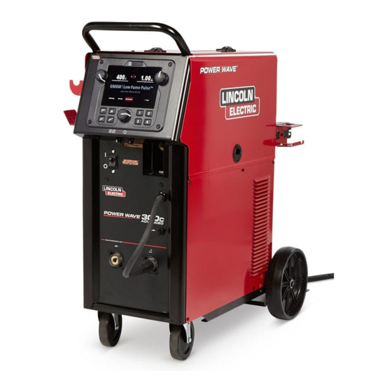
Operator's Manual
POWER WAVE
Register your machine:
www.lincolnelectric.com/register
Authorized Service and Distributor Locator:
www.lincolnelectric.com/locator
Save for future reference
Date Purchased
Code: (ex: 10859)
Serial: (ex: U1060512345)
IM10591
| Issue D ate Oct - 20
© Lincoln Global, Inc. All Rights Reserved.
300C
®
For use with machines having Code Numbers:
12942, 12943, 12944, 12945
Advertisement
Table of Contents

Related Manuals for Lincoln Electric POWER WAVE 300C


Summary of Contents for Lincoln Electric POWER WAVE 300C
- Page 1 Operator’s Manual POWER WAVE 300C ® For use with machines having Code Numbers: 12942, 12943, 12944, 12945 Register your machine: www.lincolnelectric.com/register Authorized Service and Distributor Locator: www.lincolnelectric.com/locator Save for future reference Date Purchased Code: (ex: 10859) Serial: (ex: U1060512345) IM10591 | Issue D ate Oct - 20 ©...
- Page 2 THANK YOU FOR SELECTING A QUALITY PRODUCT BY KEEP YOUR HEAD OUT OF THE FUMES. DON’T get too close to the arc. LINCOLN ELEC TRIC. Use corrective lenses if necessary to stay a reasonable distance away from the arc. READ and obey the Safety Data PLEASE EXAMINE CARTON AND EQUIPMENT FOR Sheet (SDS) and the warning label DAMAGE IMMEDIATELY...
- Page 3 W117.2. A Free copy of “Arc Welding Safety” booklet E205 is available from the Lincoln Electric Company, 22801 2.d. All welders should use the following procedures in order to St. Clair Avenue, Cleveland, Ohio 44117-1199.
- Page 4 SAFETY ELECTRIC SHOCK ARC RAYS CAN BURN. CAN KILL. 3.a. The electrode and work (or ground) circuits are 4.a. Use a shield with the proper filter and cover plates to protect your electrically “hot” when the welder is on. Do eyes from sparks and the rays of the arc when welding or not touch these “hot”...
- Page 5 SAFETY WELDING AND CUTTING CYLINDER MAY EXPLODE IF SPARKS CAN CAUSE DAMAGED. FIRE OR EXPLOSION. 7.a. Use only compressed gas cylinders containing the correct shielding gas for the process used 6.a. Remove fire hazards from the welding area. If and properly operating regulators designed for this is not possible, cover them to prevent the welding sparks the gas and pressure used.
- Page 6 PRÉCAUTIONS DE SÛRETÉ 5. Toujours porter des lunettes de sécurité dans la zone de Pour votre propre protection lire et observer toutes les instruc- soudage. Utiliser des lunettes avec écrans lateraux dans les tions et les précautions de sûreté speci ques qui parraissent zones où...
- Page 7 EN 60974-10 Electromagnetic Compatibility (EMC) Product Standard for Arc Welding Equipment. It is for use with other Lincoln Electric METHODS OF REDUCING EMISSIONS equipment. It is designed for industrial and professional use.
-
Page 8: Table Of Contents
TABLE OF CONTENTS Page Installation........................Section A Technical Specifications ....................A-1, A-2 Safety Precautions .......................A-3 Location, Lifting ......................A-3 Stacking ........................A-3 Tilting..........................A-3 Input and Ground Connections ..................A-3 Machine Grounding.......................A-3 High Frequency Protection....................A-3 Input Connection ........................A-4 Input Fuse and Supply Wire..................A-4 Input Voltage Selection ....................A-4 Power Cord Replacement .....................A-4 Connection Diagram .....................A-5 Recommended Work Cable Sizes ................A-5... - Page 9 TABLE OF CONTENTS Page Maintenance ....................Section D Safety Precautions .......................D-1 Routine Maintenance ......................D-1 Periodic Maintenance......................D-1 Calibration Specification.......................D-1 ________________________________________________________________________________ Troubleshooting ....................Section E Safety Precautions ....................E-1 How to Use Troubleshooting Guide...............E-1 Using Status LED and Error Fault Codes ..............E-2, E-4 Troubleshooting Guide ................E-2 thru E-5 Error Fault Codes ......................E-6, E-7 ________________________________________________________________________________ Wiring Diagram and Dimension Print ............Section F...
-
Page 10: Installation
POWER WAVE 300C INSTALLATION ® TECHNICAL SPECIFICATIONS - POWER WAVE 300C STANDARD ® POWER SOURCE-INPUT VOLTAGE AND CURRENT Maximum Input Amperes Power Factor @ Model Input Voltage ± 10% Idle Power (1 Phase in parenthesis) Rated Output K4487-1 208/230/400*/460/575 39/35/22/18/14.5... - Page 11 POWER WAVE 300C INSTALLATION ® TECHNICAL SPECIFICATIONS - POWER WAVE 300C ADVANCED ® POWER SOURCE-INPUT VOLTAGE AND CURRENT Maximum Input Amperes Power Factor @ Input Voltage ± 10% Model Idle Power (1 Phase in parenthesis) Rated Output K4488-1 208/230/400*/460/575 44/40/25/20/16.5...
- Page 12 POWER WAVE 300C INSTALLATION ® WIRE FEED SPEED RANGE-WIRE SIZE GMAW GMAW GMAW FCAW ALUMINUM MILD STEEL STAINLESS WFS RANGE WIRE SIZES WIRE SIZES WIRE SIZES WIRE SIZES .025 – .045" .030 – 3/64" .035 – .045" .035 – .052"...
-
Page 13: Safety Precautions
POWER WAVE 300C INSTALLATION ® SAFETY PRECAUTIONS Read this entire installation section before you start installa- WARNING tion. • Lift only with equipment of adequate WARNING lifting capacity. • Be sure machine is stable when lifting. • Do not operate machine while suspend- ELECTRIC SHOCK can kill. -
Page 14: Input Connection
POWER WAVE 300C INSTALLATION ® INPUT CONNECTION WARNING WARNING The POWER WAVE 300C ON/OFF ® Only a qualified electrician should switch is not intended as a service connect the input leads to the disconnect for this equipment. Only POWER WAVE 300C. -
Page 15: Recommended Work Cable Sizes
POWER WAVE 300C INSTALLATION ® RECOMMENDED WORK CABLE SEMI-AUTOMATIC WELDING SIZES FOR ARC WELDING POLARITY A 15 ft. work cable is provided with the POWER Most GMAW welding procedures use Electrode WAVE 300C. This cable is appropriately sized for all Positive welding. -
Page 16: Cable Connections
POWER WAVE 300C INSTALLATION ® CABLE CONNECTIONS There are two circulars connector in the wire drive compart- ment. (See 4-pin and 12-pin---Figure A.2---Table A.1) CABLE INDUCTANCE AND ITS To minimize inductance always use the appropriate EFFECTS ON WELDING size cables, and whenever possible, run the electrode and work cables in close proximity to one another to minimize the loop area. -
Page 17: Shielding Gas Connections
POWER WAVE 300C INSTALLATION ® SHIELDING GAS CONNECTION 5. Attach one end of the inlet hose to the outlet fitting of WARNING the flow regulator. Attach the other end to the welding system shielding gas inlet. Tighten the union nuts with a wrench. -
Page 18: Loading Spool Wire
POWER WAVE 300C INSTALLATION ® LOADING SPOOLS OF WIRE WARNING • Keep hands, hair, clothing and tools away from rotating equipment. • Do not wear gloves when threading wire or changing wire spool. • Only qualified personnel should install, use or service this equipment. -
Page 19: Wire Drive Configuration
POWER WAVE 300C INSTALLATION ® WIRE DRIVE CONFIGURATION 8. Connect the shielding gas hose to the new gun bushing, if required. (See Figure A.4) 9. Rotate the gun bushing until the thumb screw hole Changing the Gun Receiver Bushing aligns with the thumb screw hole in the feed plate. -
Page 20: Gun Used
POWER WAVE 300C INSTALLATION ® GUN USED 1. Press end of gun against a solid object that is elec- trically isolated from the welder output and press the gun trigger for several seconds. The Magnum PRO CURVE 300 Ready-Pak is the ®... -
Page 21: Tig Welding
(standard model) or electrode stud (advanced output stud (standard model) or electrode stud model). (advanced model) The TIG torch gas connection should be connected to the POWER WAVE 300C’s ® Some SMAW welding procedures use Electrode internal gas supply connection. If required a foot Negative Polarity. -
Page 22: Operation
POWER WAVE 300C OPERATION ® SAFETY PRECAUTIONS GRAPHIC SYMBOLS THAT APPEAR ON THIS MACHINE OR IN THIS MANUAL READ AND UNDERSTAND ENTIRE SECTION BEFORE OPERATING MACHINE. WARNING WARNING OR CAUTION • ELECTRIC SHOCK CAN KILL. Unless using COLD FEED fea-... -
Page 23: Product Description
POWER WAVE 300C OPERATION ® PROCESS LIMITATIONS PRODUCT DESCRIPTION The software based weld tables of the Power Wave 300C ® The Power Wave 300C is a high performance multi- ® limit the process capability within the output range and the process machine with GMAW, FCAW, SMAW, DC safe limits of the machine. -
Page 24: Design Features
POWER WAVE 300C OPERATION ® DESIGN FEATURES • Patent pending dual spring pressure arms have sensitivity for feeding soft wires without crushing Loaded with Standard Features them, and have plenty of compression force for feeding solid or stiff wires. • Multiple process DC output range: 5 - 350 Amps. -
Page 25: Case Front Controls
POWER WAVE 300C OPERATION ® CASE FRONT CONTROLS - STANDARD MODEL FIGURE B.1 All operator controls and adjustments are located on 9. GUN TRIGGER CONNECTOR the case front of the Power Wave. (See Figure B.1) 10. 12-PIN REMOTE CONNECTOR 1. LEFT KNOB - Adjusts wire feed speed/Amps. - Page 26 POWER WAVE 300C OPERATION ® CASE FRONT CONTROLS - ADVANCED MODEL FIGURE B.2 All operator controls and adjustments are located on 9. GUN TRIGGER CONNECTOR the case front of the Power Wave. (See Figure B.2) 10. 12-PIN REMOTE CONNECTOR 1. LEFT KNOB - Adjusts wire feed speed/Amps.
-
Page 27: Case Back Controls
POWER WAVE 300C OPERATION ® CASE BACK CONTROLS - STANDARD AND ADVANCED MODELS FIGURE B.3 1. POWER CORD LOCATION 2. GAS CONNECTION, GMAW AND FCAW 3. GAS CONNECTION, GTAW 4. OPTIONAL - 115 VOLT, 10 AMPS 60 Hz RECEPTACLE FOR GENERAL USE - K2829-1 5. -
Page 28: Internal Controls
POWER WAVE 300C OPERATION ® INTERNAL CONTROLS - STANDARD AND ADVANCED MODELS FIGURE B.4 7. CIRCUIT BREAKER 1. SPINDLE BRAKE 8. COLD INCH / GAS PURGE SWITCH 2. WIRE DRIVE PRESSURE ARM 3. THUMB SCREW, FOR SECURING THE WELDING GUN 4. -
Page 29: Making A Weld With Waveform Technology Power Sources
The standard weld set shipped with the WFS. the Power Wave 300C encompasses a wide range of common processes that will meet most needs. If a AMPS special weld mode is desired, contact the local Lincoln In constant current modes, this control adjusts the Electric sales representative. - Page 30 OPERATION POWER WAVE 300C ® USER INTERFACE LAYOUT FIGURE B.5 1. Process Adjustment Knob: Turn to adjust setpoint (dependent on the process). 2. Process Adjustment Knob: Turn to adjust setpoint (dependent on the process). 3. Menu Knob: Turn to scroll through the menu and press to select a highlighted op�on.
- Page 31 OPERATION POWER WAVE 300C ® SIMPLIFIED HOME SCREEN FIGURE B.14 1. Memory Name 2. Menu Bar - Use the Menu knob to scroll through the op�ons along the bo�om of the screen. Press the knob to select the highlighted op�on.
- Page 32 POWER WAVE 300C OPERATION ® USER INTERFACE NAVIGATION SMAW HOME SCREEN (ADVANCED VIEW) FIGURE B.6 1. Menu Bar - Use the Menu knob to scroll through the op�ons along the bo�om of the screen. Press the knob to select the highlighted op�on.
- Page 33 OPERATION POWER WAVE 300C ® GTAW HOME SCREEN (ADVANCED VIEW) FIGURE B.7 1. Memory Name 2. Menu Bar - Use the Menu knob to scroll through the op�ons along the bo�om of the screen. Press the knob to select the highlighted op�on.
- Page 34 OPERATION POWER WAVE 300C ® GTAW START/END SETTINGS FIGURE B.8 1. Set all to Auto – Start/End se�ngs are set to “auto” by default. These se�ngs are programmed based on process and setpoint to provide ideal welding. 2. Start Time – Controls the voltage for a specified �me at the beginning of the weld. During that �me, the machine will ramp from the Start Procedure to the Welding Procedure.
- Page 35 POWER WAVE 300C OPERATION ® FCAW HOME SCREEN (ADVANCED VIEW) FIGURE B.9 1. Memory Name 2. Menu Bar - Use the Menu knob to scroll through the op�ons along the bo�om of the screen. Press the knob to select the highlighted op�on.
- Page 36 POWER WAVE 300C OPERATION ® GMAW HOME SCREEN (ADVANCED VIEW) FIGURE B.10 1. Memory Name 2. Menu Bar - Use the Menu knob to scroll through the op�ons along the bo�om of the screen. Press the knob to select the highlighted op�on.
- Page 37 POWER WAVE 300C OPERATION ® FCAW/GMAW START/END SETTINGS FIGURE B.11 1. Set all to Auto – Start/end se�ngs are set to “auto” by default. These se�ngs are programmed based on process and setpoint to provide ideal welding. The se�ngs may be adjusted if desired.
- Page 38 POWER WAVE 300C OPERATION ® SYSTEM MENU FIGURE B.12 1. USB Memory Media Connected. 2. Memories – View the saved memories for each process. 3. Language – Allows the user interface to be translated into the user's preferred language. 4. Display Units – Allows units to be displayed in metric or imperial.
- Page 39 OPERATION POWER WAVE 300C ® ADVANCED SYSTEM SETTINGS FIGURE B.13 1. So�ware Versions 2. Weld Feedback Persists 3. Weld Feedback Time 4. Home Screen Layout – Choose between Advanced and Simplified. B-18...
- Page 40 POWER WAVE 300C OPERATION ® MORE SETTINGS MENU (ALL PROCESSES) FIGURE B.15 1. Advanced process se�ngs will appear here. Each weld process will have different se�ngs. The most common advanced se�ngs are: Pinch, Arc Force, Hot Start, Pre-Flow Time, Post-Flow Time, 2-Step/4-Step Trigger, and Ul�marc.
- Page 41 OPERATION POWER WAVE 300C ® PREVIOUS SETTING INDICATOR FIGURE B.16 1. Pinch Se�ng 2. Previous Se�ng Indicator – The do�ed line will indicate where on the bar the most recent se�ng was. 3. Pinch Se�ng Indicator – Increasing the value will move the bar to the right, decreasing the value will move the bar to the le�.
- Page 42 OPERATION POWER WAVE 300C ® WELDING SCREEN FIGURE B.17 1. Memory Name 2. Weld Feedback Current 3. Weld Feedback Voltage 4. Ac�ve Weld Se�ngs 5. Dual Procedure Indicator - Displays the ac�ve welding procedure/schedule. Pressing the ac�ve process bu�on switches between the procedure/schedule op�ons.
- Page 43 POWER WAVE 300C OPERATION ® BACK/HOME BUTTONS FIGURE B.18 1. Back Bu�on - Selec�ng the back bu�on takes the system back one screen. 2. Home Bu�on – Selec�ng the home bu�on takes the system back to the home screen. B-22...
- Page 44 OPERATION POWER WAVE 300C ® MEMORY OPERATION FIGURE B.19 Memories can be saved for each welding process. These can be accessed by touching the applicable memory bu�on labeled one through four. To save a memory, hold the desired memory loca�on down un�l the screen indicates the memory is saved.
- Page 45 • Insert the USB stick into the USB port on the user interface. • Turn on the power to the Power Wave 300C and wait for the initialization sequence to complete. • A message will appear asking if you want to perform a Display Software Update.
- Page 46 POWER WAVE 300C OPERATION ® 2-STEP - 4-STEP TRIGGER OPERATION EXAMPLE 1 - 2 STEP TRIGGER: The simplest trigger operation occurs with a 2 Step trigger and the Start, Crater and Burnback functions all set to OFF. (See Figure B.19)
- Page 47 POWER WAVE 300C OPERATION ® EXAMPLE 2 - 2 STEP TRIGGER: Improved Arc Start UPSLOPE: and Arc End. Tailoring the arc start and arc end is a Once the wire touches the work and an arc is estab- common method for reducing spatter and improving lished, both the machine output and the wire feed weld quality.
- Page 48 POWER WAVE 300C OPERATION ® EXAMPLE 3 - 2 STEP TRIGGER: Customized Arc WELD: Start, Crater and Arc End. Sometimes it is advanta- After upslope, the power source output and the wire geous to set specific arc start, crater and arc ending feed speed continue at the weld settings.
- Page 49 POWER WAVE 300C OPERATION ® EXAMPLE 4 – 4 STEP TRIGGER: Trigger Interlock The 4 step trigger can be configured as a trigger inter- lock. Trigger interlock adds to the welder’s comfort when making long welds by allowing the trigger to be released after an initial trigger pull.
- Page 50 POWER WAVE 300C OPERATION ® UPSLOPE: EXAMPLE 5 - 4 STEP TRIGGER: Manual control of During upslope, the power source output and the wire Start and Crater times with Burnback ON. The 4 step feed speed ramp to the weld settings throughout the trigger sequence gives the most flexibility when the start time.
-
Page 51: Cold Feed/Gas Purge Switch
POWER WAVE 300C OPERATION ® COLD FEED/GAS PURGE SWITCH COLD FEED Cold Feed and Gas Purge are com- bined into a single spring centered tog- gle switch. To activate Cold Feeding, hold the GAS PURGE switch in the FORWARD position. The wire drive will feed electrode but neither the power source nor the gas solenoid will be energized. -
Page 52: Accessories
POWER WAVE 300C ACCESSORIES ® OPTIONS / ACCESSORIES ARC START SWITCH - POWER WAVE 300C DUAL GAS BOTTLE ® UPGRADE KIT (K4866-1) - Attaches to TIG torch for convenient finger control. Comes equipped with 12-pin connector. Order Allows for the use of multiple gas bottles or a K814-2. - Page 53 POWER WAVE 300C MAINTENANCE ® SAFETY PRECAUTIONS WARNING ELECTRIC SHOCK can kill. • Do not operate with covers removed. • Turn off power source before installing or servicing. • Do not touch electrically hot parts. • Turn the input power to the welding power source off at the fuse box before working in the terminal strip.
- Page 54 HOW TO USE TROUBLESHOOTING GUIDE WARNING Service and Repair should only be performed by Lincoln Electric Factory Trained Personnel. Unauthorized repairs performed on this equipment may result in danger to the technician and machine operator and will invalidate your factory warranty. For your safety and to avoid Electrical Shock, please observe all safety notes and precautions detailed throughout this manual.
- Page 55 Not all of the Power Wave 300C errors will be displayed on the user interface. There are three status lights that contain Included in this section is information about the Status error sequences that may not show up on the user interface.
- Page 56 POWER WAVE 300C TROUBLESHOOTING ® Observe all Safety Guidelines detailed throughout this manual ERROR CODES FOR THE POWER WAVE ® The following is a partial list of possible error codes for the POWER WAVE 300C. For a complete listing consult ®...
- Page 57 POWER WAVE 300C TROUBLESHOOTING ® Observe all Safety Guidelines detailed throughout this manual INPUT CONTROL BOARD Error Code # Indication Peak input current limit Input current limit has been exceeded. Typically indicates short term power overload. If problem persists contact Service Department.
- Page 58 POWER WAVE 300C TROUBLESHOOTING ® Observe all Safety Guidelines detailed throughout this manual PROBLEMS POSSIBLE RECOMMENDED (SYMPTOMS) CAUSE COURSE OF ACTION Basic Machine Problems Input fuses keep blowing 1. Improperly sized input fuses. 1. Make sure fuses are properly sized. See installation section of this manual for recommended sizes.
- Page 59 POWER WAVE 300C TROUBLESHOOTING ® Observe all Safety Guidelines detailed throughout this manual PROBLEMS POSSIBLE RECOMMENDED (SYMPTOMS) CAUSE COURSE OF ACTION Thermal LED is ON Improper fan operation Basic Machine Problems (Continued) Thermal LED is ON 1. Improper fan operation.
- Page 60 POWER WAVE 300C TROUBLESHOOTING ® Observe all Safety Guidelines detailed throughout this manual PROBLEMS POSSIBLE RECOMMENDED (SYMPTOMS) CAUSE COURSE OF ACTION Weld and Arc Quality Problems (Continued) Wire burns back to tip at the end of 1. Burnback Time 1. Reduce burnback time and/or the weld.
- Page 61 POWER WAVE 300C TROUBLESHOOTING ® Observe all Safety Guidelines detailed throughout this manual PROBLEMS POSSIBLE RECOMMENDED (SYMPTOMS) CAUSE COURSE OF ACTION Ethernet Cannot Connect 1. Physical connection. 1. Verify that the correct patch cable or cross over cable is being used (refer to local IT department for assistance).
- Page 62 POWER WAVE 300C DIAGRAMS ®...
- Page 63 POWER WAVE 300C DIAGRAMS ®...
- Page 64 POWER WAVE 300C DIMENSION PRINT ®...
- Page 65 POWER WAVE 300C NOTES ®...
- Page 66 WARNING Do not touch electrically live parts or Keep flammable materials away. Wear eye, ear and body protection. electrode with skin or wet clothing. Insulate yourself from work and AVISO DE ground. Spanish PRECAuCION No toque las partes o los electrodos Mantenga el material combustible Protéjase los ojos, los oídos y el bajo carga con la piel o ropa moja-...
- Page 67 WARNING Keep your head out of fumes. Turn power off before servicing. Do not operate with panel open or Use ventilation or exhaust to guards off. remove fumes from breathing zone. AVISO DE Spanish PRECAuCION Los humos fuera de la zona de res- Desconectar el cable de ali- No operar con panel abierto o piración.
- Page 68 Lincoln Electric for advice or information about their use of our products. We respond to our customers based on the best information in our possession at that time. Lincoln Electric is not in a position to warrant or guarantee such advice, and assumes no liability, with respect to such information or advice.
Need help?
Do you have a question about the POWER WAVE 300C and is the answer not in the manual?
Questions and answers