Table of Contents
Advertisement
Quick Links
LINC-MATIC CB
SAFETY INSTRUCTIONS FOR OPERATING AND MAINTENANCE
SAFETY INSTRUCTIONS FOR OPERATING AND MAINTENANCE
LINC-MATIC CB-LF: AS-XP-95240700 - AS-XP-95240701 - AS-XP-95240702 - AS-XP-95240703
LINC-MATIC CB-LF: AS-XP-95240700 - AS-XP-95240701 - AS-XP-95240702 - AS-XP-95240703
LINC-MATIC CB-LM: AS-XP-95240710 - AS-XP-95240711 - AS-XP-95240712 - AS-XP-95240713
LINC-MATIC CB-LM: AS-XP-95240710 - AS-XP-95240711 - AS-XP-95240712 - AS-XP-95240713
ISSUE
: EN
REVISION
: B
DATE
: 03 - 2022
BOOM
LM-LF
C-series
Instruction manual
REF : 8695 6061
Original instructions
Advertisement
Table of Contents

Subscribe to Our Youtube Channel
Related Manuals for Lincoln Electric LINC-MATIC CB-LF C Series


Summary of Contents for Lincoln Electric LINC-MATIC CB-LF C Series
- Page 1 BOOM LINC-MATIC CB LM-LF C-series SAFETY INSTRUCTIONS FOR OPERATING AND MAINTENANCE SAFETY INSTRUCTIONS FOR OPERATING AND MAINTENANCE LINC-MATIC CB-LF: AS-XP-95240700 - AS-XP-95240701 - AS-XP-95240702 - AS-XP-95240703 LINC-MATIC CB-LF: AS-XP-95240700 - AS-XP-95240701 - AS-XP-95240702 - AS-XP-95240703 LINC-MATIC CB-LM: AS-XP-95240710 - AS-XP-95240711 - AS-XP-95240712 - AS-XP-95240713 LINC-MATIC CB-LM: AS-XP-95240710 - AS-XP-95240711 - AS-XP-95240712 - AS-XP-95240713 ISSUE : EN...
- Page 2 Thank you very much for the trust you have shown by choosing this piece of equipment. It will give you trouble-free service if it is used and maintained as recommended. Its design, component specifications and manufacturing are in accordance with applicable European directives.
-
Page 3: Table Of Contents
Table of contents A - IDENTIFICATION ........................1 B - SAFETY INSTRUCTIONS ......................2 1 - Particular safety instructions --------------------------------------------------------------------------- 2 C - DESCRIPTION ......................... 5 1 - Description ---------------------------------------------------------------------------------------------------- 5 2 - Type of boom ------------------------------------------------------------------------------------------------- 5 3 - Column (ref.: F) ---------------------------------------------------------------------------------------------- 6 4 - Lifting (ref.: R) ------------------------------------------------------------------------------------------------ 6 5 - Sliding block (ref: C) --------------------------------------------------------------------------------------- 6 6 - Powered carriage (ref: M) -------------------------------------------------------------------------------- 6... - Page 4 10 - Electrical cabinet maintenance ----------------------------------------------------------------------36 11 - Control console maintenance ------------------------------------------------------------------------36 12 - Troubleshooting ------------------------------------------------------------------------------------------36 13 - Spare parts -------------------------------------------------------------------------------------------------37 PERSONAL NOTES ........................44 INFORMATION This technical literature is intended for the following machines or products: LINC-MATIC CB-LF 3032C •...
-
Page 5: Meaning Of Symbols
MEANING OF SYMBOLS Reading the manual/instructions Indicates a hazard. mandatory. Use of safety shoes mandatory. Warning of an electrical risk or hazard. Warning of a risk or hazard due to an Use of auditory protection mandatory. obstacle on the ground. Warning of a risk or hazard of falling, Use of safety helmet mandatory. - Page 6 LINC-MATIC CB ‘C-series’...
-
Page 7: A - Identification
A - IDENTIFICATION The information below should be provided in all correspondence. User’s guide... -
Page 8: B - Safety Instructions
Before use, the operator must make sure that there is no risk of collision with personnel. Clean the working area from time to time. This machine may only be moved by its designer, namely Lincoln Electric. Never modify the machine. - Page 9 Store cable bundles behind the electrical cabinet of the boom. The use of Personal Protective Equipment (PPE) is mandatory. Machine maintenance must be carried out with all the energy supplies switched off. The disconnection and padlocking of all energy sources is mandatory. Sliding block maintenance may only be carried out with all the energy supplies switched off, when the covers are removed.
- Page 10 Make sure that no part of the machine can come within less than 500 mm of an obstacle according to the safety standards NF EN 349. Important: the operator passage way must absolutely be clear over a minimum width of 800 mm according to safety standards NF EN 547-1-3.
-
Page 11: C - Description
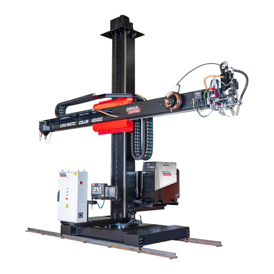
C - DESCRIPTION 1 - Description This welding boom dedicated to Submerged Arc (SA) welding makes it possible to position and move an automatic welding head. It is particularly designed for fabricating cylindrical bodies and also metal structures. 2 - Type of boom The boom is available in: LINC-MATIC CB-LF fixed version with base LINC-MATIC CB-LM powered carriage version... -
Page 12: Column (Ref.: F)
3 - Column (ref.: F) It is made up of bent mechanically welded metal. Two rolling tracks over the entire height ensure stable and smooth vertical movement of the arm support sliding block. The column has a vertical rack over its entire height, which acts as safety gear if the lifting system fails. It is fixed to the carriage or the base by means of a slewing ring with a large diameter. -
Page 13: Electrical Cabinet (Ref: A)
LINC-MATIC CB C-series. Disconnecting box: Lincoln Electric offers two types of disconnecting box depending on the number of power sources installed on the LINC-MATIC CB C-series. This box provides the electricity supply required by the installation. The function of this cabinet is to separate each of the elements in the installation from the customer’s power supply system (LINC-MATIC CB C-series, POWERWAVE etc.) -
Page 14: Dimensions And Travel Ranges Of Linc-Matic Cb-Lm Boom
13 - Dimensions and travel ranges of LINC-MATIC CB-LM boom Equipped with a single-wire submerged arc head: 360° 2030 1576 1037 1572 2010 2600 3080 1800 Equipped with a tandem submerged arc head: 360° 1156 1156 2030 1576 1037 1572 2010 2600 3080... -
Page 15: Dimensions And Travel Ranges Of Linc-Matic Cb-Lf Boom
14 - Dimensions and travel ranges of LINC-MATIC CB-LF boom Equipped with a single-wire submerged arc head: 360° 2030 1576 1800 1572 1800 Equipped with a tandem submerged arc head: 360° 1156 1156 2030 1580 1572 1800 1800 User’s guide... -
Page 16: Technical Specifications
Vertical Horizontal Height Part number Type travel travel Weight (kg) (mm) “H” (mm) “Y” (mm) “X” AS-XP-95240710 LINC-MATIC CB-LM 3032C 3000 3200 5500 6400 AS-XP-95240711 LINC-MATIC CB-LM 4042C 4000 4200 6500 6700 AS-XP-95240712 LINC-MATIC CB-LM 5052C 5000 5200 7550 7000 AS-XP-95240713 LINC-MATIC CB-LM 6062C 6000 6200... -
Page 17: D - Assembly And Installation
D - ASSEMBLY AND INSTALLATION 1 - Installation conditions The machine must be located in accordance with safety standard NF EN 547 -1 -3 to keep personnel safe. The following conditions must be fulfilled before the equipment is installed. ELECTRICITY SUPPLY see electrical diagram supplied VERY IMPORTANT The power cable (customer supply) must have a section suitable for the power rating of the installation. -
Page 18: Floor Preparation
2 - Floor preparation The floor does not need any particular preparation for installing the machine; however, we recommend a concrete floor for the machine to be satisfactorily stable. Thickness of concrete slab: 200mm • Flatness over the entire area: ± 5mm •... - Page 19 Column The column is to be lifted with two pieces of lifting equipment to avoid the pendulum effect. LINC-MATIC CB LM-LF 3032C : 2500 daN LINC-MATIC CB LM-LF 4042C : 2750 daN LINC-MATIC CB LM-LF 5052C : 3050 daN LINC-MATIC CB LM-LF 6062C : 3300 daN LINC-MATIC CB LM-LF 3032C : 580 daN LINC-MATIC CB LM-LF 4042C : 690 daN LINC-MATIC CB LM-LF 5052C : 810 daN...
- Page 20 Carriage Base 1200 daN 1500 daN Platform (1 power source version) Platform (2 power sources version) 200 daN 250 daN Electrical cabinet Guide rails LW rail (10 metres): : 260daN • LE rail (6 metres): 150 daN 150 daN • Burback rail (6 metres): 260 daN •...
-
Page 21: Installation On The Ground Of A Linc-Matic Cb Lm And
4 - Installation on the ground of a LINC-MATIC CB LM and LF 1 - Installation on rails (LINC-MATIC CB LM) Mark and drill the anchor locations. LW rail 1800 1338 1800 1000 1000 10000 The installation of LW rails makes it necessary to break in the rollers and rail combination when starting up. - Page 22 Burbach rail 1800 1330 1800 1000 1000 6000 2 - Installation of the base (LINC-MATIC CB LF) Mark and drill the anchor location as shown in the layout drawing. M16 x 175 M16 x 175 LINC-MATIC CB ‘C-series’...
-
Page 23: Reassembly Of The Linc-Matic Cb Boom
5 - Reassembly of the LINC-MATIC CB boom Before use, the operator must make sure that there is no risk of collision with personnel. While reassembling a LINC-MATIC CB LM boom, first position and anchor the tracks on the floor, place the carriage on the rails, making sure the flanged wheels are between the rails. - Page 24 Install the 2 column locking systems with the 2 M16 x 65 hex head screws each. Lock the rotation of the column Take off the plug and put the vent (in the pocket for transport) Position the slings on the arm, 2 metres away from each end and insert the rack assembly downward between the already adjusted eccentric rollers Fasten the mechanical stop with 2 M10 X 40 Allen screws and fasten the 2 electrical limit switches with 2 M 5 X 30 Allen screws...
-
Page 25: Reassembly Of The Platform And Electrical Cabinet
Make sure that the arm is level using a level placed on the arm rail. If the parallel alignment and levelling is not correct, the eccentric rollers must be adjusted; please contact the After-Sales Service department of Lincoln Electric 6 - Reassembly of the platform and electrical cabinet Install the platform with 4 M 12 X 35 hex head screws. -
Page 26: Electrical And Pneumatic Connections
7 - Electrical and pneumatic connections Connect the cables using the supplied electrical diagram. Connect the electrical and pneumatic supplies using the supplied electrical diagram. 5-7 bars 3 x 400 V See electrical diagrams: 95240790 for connecting the cabinet • 95240726 optional disconnecting box, single-wire head version (1 power source) •... - Page 27 User’s guide...
-
Page 28: E - Operating Manual
E - OPERATING MANUAL 1 - Control buttons on cabinet Power on indicator Main machine disconnector Emergency stop LINC-MATIC CB ‘C-series’... -
Page 29: Control Buttons On Operator Console
2 - Control buttons on operator console Starting up Cycle start Cycle stop Emergency stop Carriage speed potentiometer Voltage setting potentiometer Intensity/wire speed setting potentiometer SLIDEMATIC slide movement Pilot Pro (see instructions for Pilot Pro) Emergency stop RC-MATIC remote control User’s guide... -
Page 30: Rc-Matic Remote Control Buttons
3 - RC-MATIC remote control buttons Reference Condition Description Emergency stop Repeat function Wire retract Increase cycle speed Sensing On/Off Cycle start Wire feed Decrease cycle speed Function 1 Selection Function 2 Selection Cycle stop Flux test Flux recycling Laser spotlight C200 slide raising movement Boom arm raising movement C200 slide leftward movement... -
Page 31: 4- Starting Up And Shutting Down
4- Starting up and shutting down REMINDER: The operator station is located before the control console. The machine is designed to work with only one operator. POWERING UP: Set the disconnector E2 to the position I; the indicator E1 will go on. •... -
Page 32: F - Maintenance
Lincoln Electric personnel. The removal and/or replacement of mechanical components of the LINC-MATIC CB boom are FORBIDDEN. Contact the After-Sales Service department of Lincoln Electric. LINC-MATIC CB ‘C-series’... -
Page 33: Maintenance Schedule
Control Visual Cleaning Pilot Pro console *: Contact the After-Sales Service department of Lincoln Electric **: Immediate inspection in the event of an impact We recommend putting in place a traced system for tracking all your maintenance operations. User’s guide... -
Page 34: Lifting System Maintenance
3 - Lifting system maintenance Step Operation Brake Periodic inspection by the Maintenance department of the working of the brake Step Operation Reduction gear All reduction gear must be maintained to offer maximum efficiency by carrying out the scheduled maintenance operations recommended by the manufacturers. - Page 35 Step Operation Chain Visual inspection No corrosion → if corroded, the chain must be changed. • Flexibility: no stiffness or seizing of articulations → if not flexible, the chain must • be changed Cleanliness: no fouling or build-up of grease and dust → if the chain is fouled, •...
-
Page 36: Maintenance Of Safety Gear
If it is not blocked, the safety gear is not working. Contact the After-Sales • Service department of Lincoln Electric To release the block, lift the arm again with the webbing • Raise the arm using the control buttons till the webbing is no longer taut and •... -
Page 37: Sliding Block Maintenance
Step Operation Rotation brake Inspect operation. 6 - Sliding block maintenance Step Operation Roller After removing the covers of the sliding block, check the condition of the rollers (=> clean, with no damage). User’s guide... -
Page 38: Arm Maintenance
7 - Arm maintenance Step Operation Rack Brush the toothed side without adding grease. To avoid oxidation, you may apply sliding coating of the type: Adermos 800 (Molydal) Step Operation Rail Check the condition of the rails (=> clean, with no foreign body). To avoid oxidation, you may apply sliding coating of the type: ... -
Page 39: Carriage Maintenance
Step Operation Reduction gear After taking off the covers of the sliding block, carry out the following checks: visually for leaks. • visually check the overall condition of the reduction gear • 9 - Carriage maintenance Step Operation Bearing housing ... - Page 40 Step Operation Reduction gear After taking off the guard cover, verify: visually for leaks. • visually check the overall condition of the reduction gear • Step Operation Full stop Test the full stop limit switches. The triggering of a limit switch must stop the movement. Step Operation Limit switch...
- Page 41 Step Operation Pinion Check the condition of the pinions (=> clean, with no foreign body). Keep the teeth clean • Lubricate with dry lubricant such as Adermos 850 • Adjusting the teeth allowance: • - loosen the adjustment screws - put the bottom of the teeth in contact with the pinion/ring pair by manually pushing the power assembly.
-
Page 42: Electrical Cabinet Maintenance
10 - Electrical cabinet maintenance Step Operation Filter Clean the filter with compressed air Step Operation Electrical equipment Inspect and tighten all the electrical contacts 11 - Control console maintenance Step Operation Control console Clean with a moist cloth, washing up liquid or monitor cleaning foam. 12 - Troubleshooting Problem Cause... -
Page 43: Spare Parts
13 - Spare parts Ordering procedure: Almost all the parts of a machine or installation are referenced in the photographs and sketches. The descriptive tables contain three types of item: items normally held in stock: • items not held in stock: •... - Page 44 Electrical cabinet API10 KMFSC API1 API2 API3 API4 API5 API6 PUP1 CAD1 LINC-MATIC CB ‘C-series’...
- Page 45 normally held in stock. not in stock upon request. Ref. Part no Stock Order Description PC5701707 Contactor, LC1D25BD PC5705278 Motor circuit breaker, 3P 4-6.3A GV2ME10 PC5701026 Change-over contactor, 6F O+C 24VDC 12A PC5702422 Disconnector, 3P - 25A PC5706105 Transformer, 230+400V/3x42V - 1260VA PC5700236 Frequency variator, 0.55K 400TP AGL402 05F PC5701026...
- Page 46 Sliding block normally held in stock. not in stock upon request. Ref. Part no Stock Order Description DI002549 Geared motor, WR75 UF1 D30 180 B5 V6 BN80A4 DI002548 Shaft pinion P95248610 Encoder, 5000pts Complete limit switch (arm) Sliding block roller assembly (arm and column) Lateral guide roller Support roller •...
- Page 47 Lifting normally held in stock. not in stock upon request. Ref. Part no Stock Order Description Motor Reduction gear (for boom LINC-MATC CB LM-LF 3032 and AS-PS-T0300008 4042) Reduction gear (for boom LINC-MATC CB LM-LF 5052 and AS-PS-T0300012 6062) Bearing housing Bearing Motor shaft pinion...
- Page 48 Rotation normally held in stock. not in stock upon request. Ref. Part no Stock Order Description Notched ring Rotation indexing • While ordering parts, please indicate the quantity and note the number of your machine in the box above. TYPE: Number: LINC-MATIC CB ‘C-series’...
- Page 49 Carriage normally held in stock. not in stock upon request. Ref. Part no Stock Order Description Motor Reduction gear Drive pinion Carriage shaft ring Bearing housing Flanged wheel Drive shaft Idle shaft Limit switch AS-PS-95240824 Brush scraper Limit switch •...
-
Page 50: Personal Notes
PERSONAL NOTES Lincoln Electric France S.A.S. Avenue Franklin Roosevelt 76120 Le Grand Quevilly 76121 Le Grand Quevilly cedex www.lincolnelectriceurope.com LINC-MATIC CB ‘C-series’...
Need help?
Do you have a question about the LINC-MATIC CB-LF C Series and is the answer not in the manual?
Questions and answers