
Subscribe to Our Youtube Channel
Related Manuals for Lincoln Electric CITOCUT 30K


Summary of Contents for Lincoln Electric CITOCUT 30K
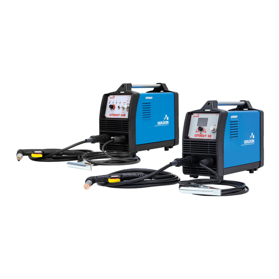
- Page 1 SVM 3185 Rev.00 02-2023 CITOCUT 30K & 45 For use with machines having code numbers: 50629 - 50631 LINCOLN ELECTRIC EUROPE www.lincolnelectric.eu...
-
Page 2: Table Of Contents
MAIN BOARD THERMAL SENSORS TEST ......................... 29 POWER BOARD VOLTAGE TEST ..........................31 DISASSEMBLY OPERATIONS ............................. 37 RETEST AFTER REPAIR .............................. 45 CALIBRATION PROCEDURE for CITOCUT 30K ......................46 CALIBRATION PROCEDURE for CITOCUT 45 ......................47 ELECTRICAL SCHEMATICS ............................48 NOTE ..................................... 50... - Page 3 TECHNICAL SPECIFICATIONS NAME INDEX CITOCUT 30K W100000319 CITOCUT 45 W100000321 INPUT Input Voltage U Input Power at Rated Output EMC Class Frequency 2,2 kW @ 100% Duty Cycle CITOCUT 30K 230V±15% 50Hz 3,3 kW @ 60% Duty Cycle 3,3 kW @ 100% Duty Cycle...
- Page 4 If any electromagnetic disturbances are detected the operator must put in place corrective actions to eliminate these disturbances with, if necessary, assistance from Lincoln Electric. Before installing the machine, the operator must check the work area for any devices that may malfunction because of electromagnetic disturbances.
- Page 5 Failure to follow the instructions in this manual could cause serious personal injury, loss of life, or equipment damage. Read and understand the following explanations of the warning symbols. Lincoln Electric is not responsible for damages caused by improper installation, improper care or abnormal operation.
- Page 6 Cutting sparks can cause explosion or fire. Keep flammables away from cutting. Do not cut or gouge near flammables. Have a fire extinguisher nearby, and have a watch person ready to use it. Do not cut on drums or any closed container. The plasma arc can cause injury and burns.
- Page 7 This machine has a protection rating of IP23S. Keep input source. it dry when possible and do not place it on wet CITOCUT 30K & 45 must be connected to a correctly ground or in puddles. installed plug-in socket with an earth pin. Input voltage ...
- Page 8 Front panel CITOCUT 30K 2. User Interface CITOCUT 45: See User Interface CITOCUT 45 chapter. 3. Work Lead Connector. 4. Compressor Internal Air Filter: ( CITOCUT 30K only). 5. Plasma Torch Connector. Rear Panel CITOCUT 30K & 45 Figure 1...
- Page 9 User Interface CITOCUT 30K User Interface CITOCUT 45 Figure 4 Figure 5 9. LED Indicator Power Switch: Lights up when 18. Home Button: Allows the user to return to the equipment is ON and connect to the the main view.
- Page 10 CITOCUT 30K Gouging CUTTING CURRENT PILOT PILOT PREFLOW POSTFLOW Figure 9 Table 2. CITOCUT 30K – Preflow/Postflow Preflow Current Postflow 15-30 A 15 s Figure 8 27. Selected grid process: To select a process, use the Active Button Control [19].
- Page 11 CITOCUT 45 – cut CITOCUT 45 – gouging After pressing the button in the torch: After pressing the button in the torch: Preflow – purge flow before ignition of the pilot Preflow – purge flow before ignition of the pilot current –...
- Page 12 CITOCUT 45 enables be cut, grid and gouging. Preparing the equipment CITOCUT 45 does not include the accessories for gauging, but the one can be purchased separately (see CITOCUT 30K enables the cutting and grid process. "Accessories" chapter). WARNING WARNING...
- Page 13 operator in his actual working conditions. Geometrical shape of the cut (whether straight or curved). Table 4. Cutting Speed CITOCUT 30K CITOCUT 30K Speed (cm/min.) Material Thickness (mm) Current(A)
- Page 14 ERRORS Table 6 Errors for CITOCUT 30K Error code Symptoms Cause Recommended Course of Action Check for air pressure are correct. Check and correct condition of fan. turn off the equipment for at least 10 minutes. Make sure the equipment ...
- Page 15 Lincoln Electric is not in a position to warrant or The frequency of the maintenance operations may vary guarantee such advice, and assumes no liability, with in accordance with the working environment where the respect to such information or advice.
-
Page 16: Thermal Protection
15 minute period. If the fan is not turning or the air intake louvers were obstructed , then the power must be switched off and the fan problem or air obstruction must be corrected. MAJOR COMPONENTS LOCATION CITOCUT 30K Fans Compressor... - Page 17 MAJOR COMPONENTS LOCATION CITOCUT 45 Air Filter Front UI Board Torch Connector Power Board Pressure Gauge Gas solenoid...
-
Page 18: Overload Protection
OVERLOAD PROTECTION operating temperature should occur, the Thermal Overload indicator on the front panel, will turn ON CITOCUT 30K & 45 are electrically protected from and the thermostat will prevent output current. producing higher than normal output current. An electronic protection circuit limits the current to The thermal protection devices are self-resetting within the capabilities of the machine. -
Page 19: Troubleshooting And Repair Section
TROUBLESHOOTING AND REPAIR SECTION How to use troubleshooting Guide Troubleshooting Guide Side panels removal and capacitor discharge procedure... - Page 20 HOW TO USE TROUBLESHOOTING GUIDE Service and repair should be performed by only Lincoln Electric Factory Trained Personnel. Unauthorized repairs performed on this equipment may result in danger to the technician and machine operator and will invalidate your factory warranty. For your safety and to avoid Electrical Shock, please observe all safety notes and precautions detailed throughout this manual.
- Page 21 WARNING 4. Test the machine to determine if the failure symptom has been corrected by the replacement PC board. NOTE: Allow the machine to heat up so that all ELECTRIC SHOCK can kill electrical components can reach their operating temperature. ...
- Page 22 TROUBLESHOOTING !! WARNING !! BEFORE CONNECT POWER SUPPLY, MAKE A CAREFUL VISUAL INSPECTION INSIDE THE MACHINE, CHECK ALL THE BOARDS AND HARNESSES. POSSIBLE AREAS OF CHECKS & RECOMMENDED COURSE PROBLEMS / SYMPTOMS MISADJUSTMENT(S) OF ACTION THE INPUT FUSES PERFORM THE INPUT RECTIFIER BRIDGE TEST ...
-
Page 23: Cover Case Removal And Dc Bus Capacitors Discharge Procedure
DISCHARGE PROCEDURE WARNING Service and repair should be performed only by Lincoln Electric factory trained personnel. Unauthorized repairs performed on this equipment may result in danger to the technician or machine operator and will invalidate your factory warranty. For your safety and to avoid electrical shock, please observe all safety notes and precautions detailed throughout this manual. - Page 24 CITOCUT 30K & 45 –COVER REMOVAL Necessary tool: PH02 screwdriver 7mm wrench Procedure: 1. Turn ON/OFF switch to OFF position. 2. Disconnect Input Power from the machine! 3. Remove the 7 screws (A) on the back panel. See above pictures 4.
-
Page 25: Discharge Procedure
DC BUS CAPACITOR DISCHARGE PROCEDURE 1. Remove main input power to the CITOCUT 30K and 45 Remove the machine cover following the case removal procedure available in this Service manual. -
Page 26: Input Rectifier Bridge Resistance Test
If for any reason you do not understand the test procedures or are unable to perform the test/repairs safely, contact your Local Lincoln Electric Service Department for electrical troubleshooting assistance before you proceed. - Page 27 Image is from CITOCUT 30K Image is from CITOCUT 45 TEST PROCEDURE 1. Remove main input power to the CITOCUT 30K or 45 2. Follow the instruction available at the Discharge procedure page. 3. Disconnect the cables from rectifier bridge terminals 4.
-
Page 28: Main Board Thermal Sensors Test
MAIN BOARD THERMAL SENSORS TEST WARNING Service and repair should be performed by only Lincoln Electric factory trained personnel. Unauthorized repairs performed on this equipment may result in danger to the technician or machine operator and will invalidate your factory warranty. For your safety and to avoid electrical shock, please observe all safety notes and precautions detailed throughout this manual. - Page 29 Using the multi-meter (ohm mode) check PTC ”OT1” and PTC ”OT2”, value shall be between 12Kohms and 15Kohms. See Figure 1 for correct locations on CITOCUT 30K Control PCB and see Figure2 for correct locations on CITOCUT 45 Control PCB...
-
Page 30: Power Board Voltage Test
POWER BOARD VOLTAGE TEST WARNING Service and repair should be performed by only Lincoln Electric factory trained personnel. Unauthorized repairs performed on this equipment may result in danger to the technician or machine operator and will invalidate your factory warranty. For your safety and to avoid electrical shock, please observe all safety notes and precautions detailed throughout this manual. - Page 31 Use always electrically insulate gloves during this test procedure 1. Carefully apply 230Vac +/- 15% input voltage via the input cable to the CITOCUT 30K or 45 2. Switch to ON position the mains switch located on the back of the machine 3.
- Page 32 Use always electrically insulate gloves during this test procedure 1. Carefully apply 230Vac +/- 15% input voltage via the input cable to the CITOCUT 30K or 45 Switch to ON position the mains switch located on the back of the machine...
- Page 33 Use always electrically insulate gloves during this test procedure 1. Carefully apply 230Vac +/- 15% input voltage via the input cable to the CITOCUT 30K or 45 2. Switch to ON position the mains switch located on the back of the machine 3.
- Page 34 Use always electrically insulate gloves during this test procedure 4. Carefully apply 230Vac +/- 15% input voltage via the input cable to the CITOCUT 30K or 45 5. Switch to ON position the mains switch located on the back of the machine 6.
- Page 35 Use always electrically insulate gloves during this test procedure 1. Carefully apply 230Vac +/- 15% input voltage via the input cable to the CITOCUT 30K or 45 2. Switch to ON position the mains switch located on the back of the machine 3.
-
Page 36: Disassembly Operations
DISASSEMBLY OPERATIONS MAIN PCB REMOVAL AND REPLACEMENT PROCEDURE (30K & 45) Figure 1 REMOVAL PROCEDURE Necessary tools: - Pliers - PH02 screwdriver 1. Remove main input power to the machine 2. Remove the cover of the machine following the cover removal procedure. 3. - Page 37 7. Remove the 4 screws (A) using the PH02 screwdriver from the fan you need to replace. 8. Carefully remove the fan from the machine. 9. For the fans re-assembly operations, make the previous steps in the reverse order. NOTE: perform the same above operations to remove the second fan present inside the CITOCUT 30K...
- Page 38 DISASSEMBLY OPERATIONS GAS SOLENOID REPLACEMENT PROCEDURE Figure 1 Figure 2 REMOVAL PROCEDURE Necessary tools: - Pliers - PH02 screwdriver 1. Remove main input power to the machine 2. Remove the cover of the machine following the cover removal procedure. 3. Follow the instruction available at the Discharge procedure page. 4.
- Page 39 DISASSEMBLY OPERATIONS FRONT PANEL BOARD REMOVAL AND REPLACEMENT PROCEDURE CITOCUT 45 Figure 2 Figure 1 REMOVAL PROCEDURE Necessary tools: Figure 3 - PH02 screwdriver - 7mm socket wrench - Pliers 1. Remove main input power to the machine 2. Remove the cover of the machine following the cover removal procedure. 3.
- Page 40 DISASSEMBLY OPERATIONS FRONT NAMEPLATE ASSEMBLY REMOVAL AND REPLACEMENT PROCEDURE CITOCUT 30K Figure 1 REMOVAL PROCEDURE Necessary tools: - PH02 screwdriver 1. Remove main input power to the machine 2. Remove the cover of the machine following the cover removal procedure.
- Page 41 7. Remove all the connectors from the Board 8. Using the Phillips screwdriver remove the 2 screws (C). 9. Carefully remove the Board from the machine. 10. For the CITOCUT 30K front panel board re-assembly operations, make the previous steps in the reverse order.
- Page 42 DISASSEMBLY OPERATIONS FRONT PANEL REMOVAL AND REPLACEMENT PROCEDURE CITOCUT 30K REMOVAL PROCEDURE Necessary tools: - PH02 screwdriver 1. Remove main input power to the machine 2. Remove the cover of the machine following the cover removal procedure. 3. Follow the instruction available at the Discharge procedure page.
- Page 43 DISASSEMBLY OPERATIONS COMPRESSOR REMOVAL AND REPLACEMENT PROCEDURE CITOCUT 30K Figure 1 REMOVAL PROCEDURE Necessary tools: - PH02 screwdriver - 12mm wrench 1. Remove main input power to the machine 2. Remove the cover of the machine following the cover removal procedure.
-
Page 44: Retest After Repair
25A@100% CITOCUT 45 230Vac/1ph/50Hz 23 max 30A@100% Output cutting current range 15-30 Amps – CITOCUT 30K 15-45 Amps – CITOCUT 45 Maximum Open Circuit Voltage U 0 peak 396 Vp ! IMPORTANT ! After the repair, the unit shall be tested accordingly to the norm EN60974-4... -
Page 45: Calibration Procedure For Citocut 30K
CALIBRATION PROCEDURE for CITOCUT 30K Calibrate the Min and Max current: 1. Add a 10K resistor between PIN3 and PIN9 of torch connector, then turn on the machine; 2. Machine switch into TEST mode; short the PIN4 and PIN7 of torch connector;... -
Page 46: Calibration Procedure For Citocut 45
CALIBRATION PROCEDURE for CITOCUT 45 Calibrate the Min and Max current: 1. Keep Push both two buttons on front panel and turn on the machine; 2. Machine switch into TEST mode; short the PIN4 and PIN7 of torch connector; 3. Connect proper pressure air into machine; 4. -
Page 47: Electrical Schematics
ELECTRICAL SCHEMATICS Block Diagram CITOCUT 30K... - Page 48 ELECTRICAL SCHEMATICS Block Diagram CITOCUT 45...
-
Page 49: Note
NOTE...
Need help?
Do you have a question about the CITOCUT 30K and is the answer not in the manual?
Questions and answers