Table of Contents
Advertisement
Quick Links
Advertisement
Table of Contents

Related Manuals for Renac RENA1000 Series


Summary of Contents for Renac RENA1000 Series
- Page 1 RENA1000 Series User Manual RENA1000-E...
-
Page 3: Table Of Contents
RENA1000 User Manual Content 1. About this Manual ..............................3 1.1 Applicability ..............................3 1.2 Target Group ............................... 3 1.3 Symbols Used ............................. 3 1.4 Designation in the Document ........................4 2.Safety ................................. 4 2.1 General Safety ............................. 4 2.2 Important Safety Instructions ........................5 2.3 Explanation of Symbols .......................... - Page 4 RENA1000 User Manual 4.6.1 Electrical Safety..........................30 4.6.2 Connecting Battery Communication Cable ..................31 4.6.3 Connecting Battery Power Cable .......................31 4.6.4 Connecting PCS Communication Cable .................... 32 4.6.5 Connecting PCS Power Cable ......................33 4.6.6 Connecting PCS AC Cable ........................ 33 4.6.7 Connecting Mains ..........................
-
Page 5: About This Manual
RENA1000 User Manual 1. About this Manual 1.1 Applicability Please read the product manual carefully before installation, operation or maintenance. This manual mainly introduces the product information, installation and wiring, configuration and debugging, troubleshooting and maintenance of the outdoor C&I energy storage system (hereinafter referred to as the energy storage system). -
Page 6: Designation In The Document
RENA1000 User Manual NOTE! 'Note' provides tips that are valuable for the optimal operation of the product. Table 1-1 Symbols used 1.4 Designation in the Document Designation in this document Designation in this document complete description Static Transfer Switch Energy Management System Battery Management System Battery Management Unit Battery Control Unit... -
Page 7: Important Safety Instructions
RENA1000 User Manual The battery cabinet is equipped with an automatic fire extinguishing system and the fire switch should not be triggered unless it is an emergency. 2.2 Important Safety Instructions DANGER! The equipment has a high voltage, and irregular operation may cause electric shock or fire, resulting in death, personal injury, or property damage. - Page 8 firefighters to extinguish the fire. ◆ Damage to the energy storage system due to under voltages · If the energy storage system doesn't start at all, please contact Renac after-sales service within 48 hours. Otherwise, the battery could be permanently damaged.
-
Page 9: Explanation Of Symbols
RENA1000 User Manual NOTE! ◆ Electrical installation and maintenance must be carried out by competent electricians according to local regulations. Table 2-2 Important safety instructions 2.3 Explanation of Symbols Symbols on Label: Symbol Explanation TUV mark Do not disconnect or disassemble by untrained personnel. Do not short circuit. -
Page 10: Electrical Safety
RENA1000 User Manual 2.4 Electrical Safety 2.4.1 Wiring Requirements Please select the cable that meets the requirements of local laws and regulations. The same type of cables should be tied together, different types of cables should be placed separately, and mutual winding or cross-laying should be prohibited. When the wiring is completed or left for a short time during the wiring process, it is necessary to immediately block the ... -
Page 11: Mechanical Safety
RENA1000 User Manual maintenance is carried out. WARNING! Before connecting the cable, it is necessary to confirm that the line label identification is correct before connecting. If the device has multiple inputs, all inputs of the device should be disconnected, and the device can be operated after the device is fully powered down. -
Page 12: Maintenance And Replacement
RENA1000 User Manual Battery beyond the warranty period. Battery exception handling measures: When electrolyte leakage or abnormal odor occurs, avoid contact with the leaked liquid or gas. Non-professionals, please do not approach; please contact the professionals immediately. The electrolyte is corrosive, and contact may cause skin irritation and chemical burns. If you come into contact with the ... -
Page 13: Arc Protection
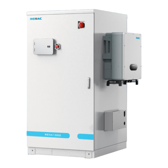
Product line - Cell model 3.2 Product Overview RENA1000 series outdoor energy storage cabinet integrates an energy storage battery, PCS, energy management monitoring system, power distribution system, environmental control system, and fire control system. PCS is used to facilitate maintenance and expansion. -
Page 14: System Chart
RENA1000 User Manual 3.3 System Chart Figure 3-1 Energy storage cabinet system block diagram 3.4 Product Characteristic 3.4.1 Mechanical Parameters Figure 3-2 Battery cabinet diagram 3.4.2 Product Characteristic System productization, integrated energy storage battery, PCS, energy management monitoring system, power distribution system, environmental control system, fire control, etc., to fully control the system operation status and risk. -
Page 15: Technical Data
RENA1000 User Manual Configure rack-type modular PCS, support multi-machine parallel, good scalability; according to the system capacity requirements of microgrid and other scenarios, the number of PCS modules and the total battery power can be selected, and the typical configuration is 83kWh/94kWh/104kWh. IP55 protection level is the perfect response to all types of outdoor weather. -
Page 16: Parts Introduction
RENA1000 User Manual Max. Efficiency 97.5% Protection Reverse Connection Protection DC Switch Over-Temperature Protection Grid Monitoring / Earthing Fault Detection Insulation Monitoring DC / AC Surge Protection DC Type ll; AC Type lll General Data Dimensions (W * H * D) 1330*1950*1425mm Weight 1400kg... -
Page 17: Battery Management System
RENA1000 User Manual Weight 1325kg Installation site Outdoor IP protection IP55 Operation humidity 5%~95% (No condensing) -20℃~+55℃ Operation temperature ≤ 2000m Max. operation altitude Communication port Ethernet; CAN Communication protocol CAN; MODBUS TCP / IP Cooling method Air conditioner Standards IEC62619;... -
Page 18: Pcs
RENA1000 User Manual 3.6.3 PCS Figure 3-4 Dimensions of N3-HB-50.0 model Model N3-HB-50.0 PV Input Data Max. PV Input Voltage[V] 1000 MPPT Voltage Range[V] 350 ~ 800 No. of MPP Tracker No. of Input Strings per Tracker 2 / 2 / 2 Max. -
Page 19: Environmental Control System
RENA1000 User Manual Power Factor adjustment range 1 (leading) ~ 1(lagging) < 3% THDv(@Rated Output) AC Outout Data(Off Grid) Max. input active power[W] 50000 Rated AC Current[A] Rated AC Voltage/Voltage Range[V] 3 / N / PE, 230 / 400; ±3% Rated Grid Frequency[Hz] 50 / 60 >... - Page 20 RENA1000 User Manual Smoke detector Travel switch DC low-tension distribution Battery Pack Fire protection system Breaker Water sensor Figure 3-5 3.6.4.1 Smoke Detector The detector is a non-coding type, which is directly connected to the DC power supply when working. When working normally, the working indicator light flashes.
- Page 21 RENA1000 User Manual 3.6.4.2 Water Sensor The water sensor is a new type of water immersion transmitter installed on the split guide rail of the contact monitoring and protection probe, which is mainly used to determine whether there is a danger of water accumulation at the contact point of the examination.
-
Page 22: Isolation Transformer (Optional)
RENA1000 User Manual 3.6.4.5 External Air Conditioner Figure 3-6 The external air conditioner is used to dissipate heat from the energy storage system. Configuring this air conditioner can provide a stable and suitable temperature and humidity environment for the energy storage system. Model External air conditioner -40℃... -
Page 23: Package And Storage
RENA1000 User Manual Insulation level Class H Efficiency 97.8% -25℃ ~ 50℃ Operation Temperature Range ≤ 3000m Operation Altitude Enclosure IP65 Size(Width* Height * Depth) 700*800*550mm Weight 260kg Table 3-8 Isolation transformer parameters 3.7 Package and Storage 3.7.1 Package The packing of the Outdoor C&I Energy storage system is mainly composed of the packages of the battery packs and the battery cabinet. -
Page 24: Storage Environment
RENA1000 User Manual BAT- BAT- Out-of-cabinet PCS Out-of-cabinet B- power communication cable*1 PCS Outside Cabinet AC*1 line*2 Stainless Steel Cross Stainless Steel Cross Hexagon Screw M6*12mm*40 Hexagon Screw M5*10mm*10 Door key*4 Air conditioning Display Key*1 Lifting Components*4 accessories*1 User Manual*1 Figure 3-7 Package 3.7.2 Storage Environment If it isn't installed immediately after the delivery work is successfully completed, please properly store the RENA1000-E according... -
Page 25: System Installation
RENA1000 User Manual If it must be stored outdoors due to on-site conditions, the RENA1000-E must be raised. The specific elevation height should be reasonably determined according to the site’s geological and meteorological conditions. If the ambient temperature is too low, heating should be provided for the internal equipment of the RENA1000-E. Storage environment temperature: -20°C~50°C(less than one month);... -
Page 26: Product Transport
Before installing the product, you need to check whether the product is intact and undamaged. If you find any traces of damage, please keep the evidence and contact RENAC Power Technology Co., Ltd. If users are sure that there are no abnormalities in the product, please check that the accessories are complete according to... -
Page 27: Mechanical Installation
RENA1000 User Manual Users need to prepare the relevant installation tools before installation. Refer to Table 4-1. Before installation, the operator should be regulated to wear a helmet, insulated clothing, insulated gloves, and insulated boots. Tool Function Quantity Screwdriver set Wiring 1 set Sleeve set... - Page 28 RENA1000 User Manual Figure 4-2 Basic reference Position the equipment on the foundation with a forklift, align the equipment, fix holes with the pre-embedded nuts of the foundation, and tighten with M12 bolts. 4-Φ14mm Figure 4-3 Bottom of the battery cabinet Open the battery cabinet and take out the Battery packs.
- Page 29 RENA1000 User Manual Figure 4-4 Move the battery pack onto a forklift or lifting device equipped with a installation jig. The manufacturer's after-sales service provides the installation jig. The installation jig is subject to the availability of after-sales service. Figure 4-5 Use the forklift or the elevating devices to install each battery pack into the battery cabinet from bottom to top.
- Page 30 RENA1000 User Manual Battery pack 1 Figure 4-6 Use M6*12 screws to fix the battery packs. 7N.m Figure 4-7 Open the PCS package and install the bracket in the upper right position of the battery cabinet. PCS installation instructions can also be detailed in the PCS User Manual.
- Page 31 RENA1000 User Manual 7N.m Figure 4-8 Hang the PCS on the bracket. There are fixing holes at the bottom of the power conversion system, which are used to fix the system on the bottom supporting channel steel or on the ground. Install the junction box in the wiring location below the PCS.
-
Page 32: Electrical Connection
4.6 Electrical Connection Electrical cabling is required in the field for the DC and AC sides as well as for external power and communications. Renac Power provides the wiring reference in Table 4-2 according to the product power and cable specification. Cable diameters should be selected in accordance with local cable standards. -
Page 33: Connecting Battery Communication Cable
RENA1000 User Manual Ensure that the energy storage system is completely de-energized when using a multimeter. Make the necessary grounding. Insulate and cover potentially live parts adjacent to the operating part with insulating cloth. 4.6.2 Connecting Battery Communication Cable One end of the communication cable for the Battery packs are already fitted in the cable slot; simply plug the end fitted with the 14Pin terminal into the corresponding battery box from bottom to top. -
Page 34: Connecting Pcs Communication Cable
RENA1000 User Manual Figure 4-11 4.6.4 Connecting PCS Communication Cable Connect the COM port on the PCS to the COM port inside the wire box. The communication cable can be found in the package. Figure 4-12... -
Page 35: Connecting Pcs Power Cable
RENA1000 User Manual 4.6.5 Connecting PCS Power Cable Connect BAT+ on the PCS to BAT+ on the wire box and BAT- on the PCS to BAT- on the wire box. Take care to look at the positive and negative terminals of the wiring harness. Out-of-cabinet power harnesses can be found in the package. Figure 4-13 4.6.6 Connecting PCS AC Cable Connect the AC wire to the AC INPUT of the PCS. -
Page 36: Connecting Mains
RENA1000 User Manual 4.6.7 Connecting Mains The inlet and outlet of the energy storage system are the bottom inlet and outlet, open the rear door of the cabinet, the wiring terminal is at the right bottom as shown in Figure 4-15. Connect L1/L2/L3/N/PE wires to the top lower row of the wiring terminal. The other end should be connected to the grid distribution box. -
Page 37: Meter Connection
RENA1000 User Manual Figure 4-16 Outside cabinet wiring diagram 4.6.7 Meter Connection Load RENA1000-E Grid 4G/WIFI/RJ45 CT direction: P1 side: Grid P2 side: Load Cloud Platform/APP Meter Figure 4-17 Electrical connection diagram The energy storage system adopts DTSD1352-CT smart meter. The connect steps are as follows: Connect the meter output "Ua, Ub, Uc, N"... - Page 38 RENA1000 User Manual 1 channel communication Figure 4-18 Meter wiring schematic NOTE! CT is not standard and has to be purchased by the customer. Recommended models are shown in the table below: Rated current ratio Accuracy class 200 / 5 (1) The P1 side of the CT is connected to the grid and the P2 side is connected to the load.
-
Page 39: Isolation Transformer Installation(Optional)
RENA1000 User Manual 4.7 Isolation Transformer Installation(Optional) Figure 4-19 Off-grid electrical schematic... -
Page 40: Start-Up And Commissioning
RENA1000 User Manual As shown in Figure 4-19, the off-grid function refers to the addition of an isolation transformer between the PCS and the grid side to ensure that the PCS can still ensure power supply to the loads if the grid side is unable to supply power for some reason. Referring to the off-grid electrical schematic diagram, the side of the transformer without the N wire is connected to the grid side of the PCS, and the other end of the transformer is connected to the molded case circuit breaker (main circuit breaker) so that the off-grid function can be realized automatically. -
Page 41: Boot Operation
RENA1000 User Manual Reserve switch Fan power switch Air conditioner power switch Main power switch Breaker Isolation switch Figure 5-1 Distribution switch location diagram 5.2 Boot Operation The product start-up operation process is as follows: After confirming that the cables are connected correctly, switch on both PCS battery switches and the PV switch if using Turn breaker to ON to connect to the grid. -
Page 42: Switch Off
RENA1000 User Manual The device control mode is set to "Battery Backup" and the active power is set to 5.0. Observe the screen PCS, battery, and air-conditioning parameters during operation, and stop the machine promptly for testing if there is any abnormality. Allow the device to run for 0.5 hours. - Page 43 RENA1000 User Manual Figure 6-1 Home page Items expanded by menu: Name of the menu Menu items Parametric function Displays the operating status of the system and the Home None charging/discharging graph of the day. PCS data PCS related data Battery data Battery related data Detail...
-
Page 44: Switchgear Operation
RENA1000 User Manual 6.2 Switchgear Operation System open: first, check the whole machine on the power situation, refer to Figure 5-1, close the breaker, and then close the switch for air conditioning and fan power supply. At this time, the screen lights up, observe the touch screen without fault alarm (screen startup takes about 10 seconds), click on the screen in the "operation", click on the operation interface in the "BMS turn high vol"... -
Page 45: Run Mode Setting
RENA1000 User Manual Figure 6-3 Communicate setting page 6.4 Run Mode Setting 6.4.1 Introduction of the Modes The run mode of the energy storage system can be divided into four: Manual Mode, Self use Mode, Time Mode, and Backup Mode. 6.4.2 Manual Mode Click "Setting"... -
Page 46: Self Use Mode
RENA1000 User Manual Users click "Save", and need to enter the password "888888" to save. Figure 6-5 6.4.3 Self Use Mode Click "Setting" -> "Run Mode", and then click "Self Use Mode" button to enter the settings page. This mode is applicable to the areas with low subsidies and high electricity prices. When the PV power is sufficient, PV power will supply the following sequence: ... -
Page 47: Time Mode
RENA1000 User Manual 6.4.4 Time Mode Click "Setting" -> "Run Mode", and then click "Time Mode" button to enter the settings page. Applicable to the areas with large gaps between peak and valley electricity prices. Users can set a time-based schedule to charge or discharge the battery by App or display screen. -
Page 48: Parameter Setting
RENA1000 User Manual Figure 6-8 Backup Mode page 6.5 Parameter Setting Click "Setting"->"Para-set" to enter the current page. This interface is usually set up in the factory, and users do not need to set it up. Figure 6-9 Parameter setting page NOTE! PCS and battery parameters are set before the energy storage system is shipped from the factory and are not recommended to be modified. -
Page 49: Data Viewing And Exporting
RENA1000 User Manual 6.6 Data Viewing and Exporting Click "Log" to enter the current page. Figure 6-10 Log page View the current day, month, year, and total charge/discharge. Insert the USB stick, wait for the USB stick to be connected, click on "Export db", and wait for some time for the export to finish. -
Page 50: Environment Monitoring Interface Introduction
RENA1000 User Manual Figure 6-11 Update page 6.8 Environment Monitoring Interface Introduction Click "Detail"->"Env state" to enter the following interface, where you can view the real-time environmental status of the system, air-conditioning parameter settings, and air-conditioning on and off. Refrigeration mode: when the temperature is greater than or equal to the set refrigeration point, air-conditioning refrigeration on when the temperature is lower than the refrigeration point minus the difference between the air-conditioning refrigeration off, the difference between the default value of 5℃... -
Page 51: App Download And Operation
7. APP Download and Operation 7.1 Download Mobile App There are two ways to download Renac SEC: Download and install <Renac SEC> mobile app by scanning the QR code below. Download <Renac SEC> from Apple Store / Google Play. Figure 7-1 7.2 Device Registration... -
Page 52: Parameter View And Run Mode Configuration
RENA1000 User Manual Figure 7-3 Click "+" and scan the QR code (charger serial number) on the device label to add a device.) Figure 7-4 After adding the power station, back to the home page, and the newly added power station will be shown in the station list. NOTE! The EMS needs to be restarted after the station has been successfully added. -
Page 53: Run Mode Configuration
RENA1000 User Manual Figure 7-5 Click on the third item "Statistics" to view the detailed parameters of the current device. Figure 7-6 7.3.2 Run Mode Configuration Click on the second item "Setting" to enter the setting interface. Users can configure the working mode of RENA1000-E. The settings on the App are the same as those on the EMS. - Page 54 RENA1000 User Manual Figure 7-7 Setting page Click "Manual Mode" to enter the settings interface. Figure 7-8 Manual mode Click "Self use Mode" to enter the setting interface. Figure 7-9 Self use mode...
-
Page 55: Parallel System On Grid
RENA1000 User Manual Click "Time Mode" to enter the setting interface. Figure 7-10 Time mode Click "Backup Mode" to enter the setting interface. Figure 7-11 Backup mode 8. Parallel System on Grid When the users have larger PV panels, and 104.4kWh is not enough to meet the power supply requirements, connecting multiple energy storage systems in parallel on the AC side is recommended. - Page 56 RENA1000 User Manual Load RENA1000-E The number of slaves Slave is not exceeding 4. CT direction: P1 side: Grid Grid P2 side: Load AC-side paralleling RENA1000-E 4G/WIFI/RJ45 Master Cloud Platform/APP Meter Figure 8-1 Parallelism of RENA1000 Installation steps: Select a suitable environment and ground according to section 4.1, and the site area meets the installation distance. The installation distance is as shown in the Figure 8-2.
-
Page 57: Troubleshooting
RENA1000 User Manual Figure 8-3 Set the master or slave in the communication setting screen of EMS. Refer to section 6.3. 9. Troubleshooting Alarm levels are defined as follows: Failure: The equipment fails, and the system stops running (charging/discharging); Alarm: the output power of the device decreases, or part of its function fails due to external factors, but it does not affect the charging/discharging function of the system. - Page 58 RENA1000 User Manual underfrequency fault grid-connected side grid-connected side Islanding protection Abnormal grid-connected Check for abnormalities in the voltage on the Grid / Tanker fault side voltage grid-connected side. High / low voltage ride Abnormal grid-connected Check for abnormalities in the voltage on the Grid / Tanker through alarm side voltage...
-
Page 59: Routine Maintenance And Warranty
RENA1000 User Manual Interruption cable between modules is loose and abnormal; malfunction 2. Check whether the local controller communication network cable is loose and abnormal. 1. Check the parallel cable for looseness or Parallel / Parallel / synchronized abnormality; synchronization fault signal interrupt 2. -
Page 60: Routine Maintenance
RENA1000 User Manual 10.1 Routine Maintenance There are a number of potential problems that can occur during system operation due to ambient temperature, humidity, dust, vibration, and aging of the inverter's internal components. In order to enable the energy storage system to operate in a long-term and stable manner, it is necessary to arrange for regular inspections by maintenance personnel, according to Table 9-1, so as to identify and deal with problems in a timely manner. -
Page 61: Warranty
10.2.2 Warranty Coverage As long as the product is in the warranty period, where the quality of the product itself leads to failure, Renac Power Technology Co., Ltd. allows customers to carry out free repair or replacement products. Users shall reserve a reasonable response time for the Company's repairs, and the Company shall handle the replacement. - Page 62 User Manual Download Center www.renacpower.com 422-00223-00...
Need help?
Do you have a question about the RENA1000 Series and is the answer not in the manual?
Questions and answers