Table of Contents
Advertisement
Quick Links
Advertisement
Table of Contents

Related Manuals for Renac R3 LV Series


Summary of Contents for Renac R3 LV Series
-
Page 2: Table Of Contents
Content 1. Introduction ................................. 2 1.1 Introduction ..............................2 1.2 Applied designations ........................... 2 1.3 Important safety information ........................2 1.4 System sizing ............................... 3 2. Technical description of inverters ........................3 2.1 Mechanical design ............................3 2.2 Electrical system design ..........................5 2.3 Technical data .............................. -
Page 3: Introduction
1. Introduction 1.1 Introduction This manual describes solar inverters: NAC10K-LV/NAC12K-LV/NAC15K-LV/NAC20K-LV. These inverters are transformerless based inverter. Please read the safety instructions in this manual first. Throughout the manual it is assumed that the reader is familiar with AC and DC installations and knows the rules and regulations for electrical equipment and for connecting it to the utility AC grid. -
Page 4: System Sizing
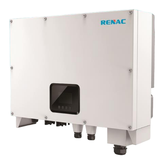
The limitation depends mainly on internal and ambient temperatures. The limitation is calculated continuously and always allows the maximum possible amount of energy to be produced. Please use the tool supplied by Renac Power when dimensioning a photovoltaic system. 2. Technical description of inverters 2.1 Mechanical design... - Page 5 Figure 2-2 shows the electrical terminals of NAC10K-LV/NAC12K-LV/NAC15K-LV/NAC20K-LV. Figure 2-2 Electrical Terminals DC Switch DC (PV terminal) Communication port AC terminal LEDs Display screen Keys For safety reasons, the use of a DC switch is recommended. Between the PV modules and the power modules may be mandatory in some countries.
-
Page 6: Electrical System Design
2.2 Electrical system design Figure 2-3 wiring diagram of the inverter system Please refer to chapter 3 for the detail connecting and install methods. 2.3 Technical data Model NAC10K-LV NAC12K-LV NAC15K-LV NAC20K-LV DC Input Data Max. Recommended PV Power 16900W 20800W 22100W 26000W... - Page 7 Residual Current Monitoring Integrated Over-heat Protection Integrated AC Overcurrent Protection Integrated AC Short-circuit Protection Integrated AC Overvoltage Protection Integrated DC Surge Protection Integrated(Type II) AC Surge Protection Integrated(Type II) General Data Size(Width*Height*Depth) 660×460×255mm Weight 38KG User Interface Communication RS485(Standard), Wifi or GPRS -25 ℃...
-
Page 8: Grid Codes
2.4 Grid codes National/Regional Grid Code Description Germany power Grid, meet Grid standards “VDE-AR-N-4105”. VDE4105-DE CEI0-21 Italy power Grid. AS4777 Australia power Grid. RD1699 Spain power Grid. EN50549-TR Turkey power Grid. EN50549-DK Denmark power Grid. Greece Greece power Grid. Netherland power Grid, meet Grid standards “EN50438”. EN50549-NL C10/11 Belgium power Grid. -
Page 9: Installation And Startup
3. Installation and startup Warning! Before installation and maintenance, AC and DC side doesn’t carry electricity, but if DC side is just disconnected, capacitance still contains electricity, so please wait for at least 5 minutes to ensure the capacitors completely release the energy and inverter is not electrified. -
Page 10: Installation Position
Figure 3-2 installation environment 3.3 Installation position The installation method and mounting location must be suitable for the inverter's weight and dimensions. Mount on a solid surface. Select a well-ventilated place sheltered from direct sun radiation. Figure 3-3 installation position In consideration of heat dissipation and convenient dismantlement, the minimum clearances around the inverter should be no less than the following value Figure 3-4 Distance required of Invertors... -
Page 11: Mounting Procedure
3.4 Mounting procedure Setp1: Drill 4 Fix Ø10 holes in the wall according to the dimensions. Step2: Fix the wall mounting bracket on the wall with 4 expansion bolts in accessory bag. Setp3: Place the inverter on the wall-mounted bracket and install the fix screw. Figure 3-5 mounting the inverter... -
Page 12: Electrical Connection
3.5 Electrical connection 3.5.1 Connection to the Grid (AC output) Add breaker or fuse to AC side, the specification should be more than 1.25 times of rated AC output current. 2) The PE line of inverter should be connected to the earth, make sure the impedance of neutral wire and earth wire less than 10 ohm. - Page 13 Figure 3-7 Connect the inverter to the grid 4. Screw waterproof coupling and Screw cap nut tightly onto the cable. 3.5.2. Connection to PV string (DC input) Before connecting PV string, make sure DC switch is turned off Make sure PV string polarity confirms with DC connector, otherwise, it will cause damage to inverter Make sure the maximum open circuit voltage (Voc) of each PV string does not exceed the inverter input voltage Vmax under any condition...
- Page 14 3.5.3. RS485/ Relay/DI Please make sure the RS485 connecting cables not exceed 1000m. Communication lines must be separated from other power lines to avoid communication interference. Figure 3-9 communication interfaces Figure 3-10 RS485 in multiple series...
-
Page 15: Starting The Inverter
3.5.4. WIFI/GPRS communication By the WIFI/GPRS interface, transfer the inverter power output information, alarm information, operation state to the PC terminal or local data acquisition device. Figure 3-11 install WIFI/GPRS module Remark: 1) COM port, PIN3:A, PIN4:B. 2) For how to monitor system through WIFI/GPRS, please refer to the module user manual in detail. 3.6 Starting the Inverter Before turn on the inverter, please confirm: 1) Three phase five wires (PE/L1/L2/L3/N) cable correctly connected to the inverter AC side through AC... -
Page 16: User Interface
Starting the inverter: 1) Close the DC and AC circuit breaker; 2) If the solar panels provide enough energy, the power module will work and the LCD panel will be lit; 3) In case you are starting the inverter for the first time, the inverter needs to be commissioned. Commissioning is described on page 16,chapter 4.2. -
Page 17: Lcd Display
4.2 LCD display Menu structure: PV info Language setting Grid info Date time setting Tem info Clear energy String info Clear record System safety Input mode Total energy Day Yield Communication Month Yield Firmware update Year Yield Recovery setting Twelev Yield SFLASH_FS Init Input Password System restart... -
Page 18: Warranty
5. Warranty The standard warranty period for the inverter is 60 months from the date of installation and no more than 66 months (5.5 years) from the date of shipment from factory. 5.1 Warranty claim procedure Please report defective device with a brief error description and SN code to our service mail or service hotline for registration. -
Page 19: Appendix A: Faq (Frequently Asked Questions)
Appendix A: FAQ (Frequently asked questions) Sometimes, the PV system does not work normally; we recommend the following solutions for average troubleshooting. This can help the technician to understand the problem and take a proper action. Fault LCD display Possible actions Check whether the inverter is earthed and test impedance between PV (+) &... - Page 20 GFDI fault HMI to S fail M to S fail HMI to Cfail HwAcOCP SwAcOCP uSwAcOCP SwOCP_PV1-4 HwOCP_BST1-4 UHwOCP_BST HwBusOVP uHwBusOVP BusUVP BusOVP PLL fault BusVolt_Ublc IacRms_Ublc VacRms_Ublc DciOCP GFCI>30mA 1. Disconnect all PV (+) or PV (-) from solar panels. GFCI>60mA 2.
- Page 21 P/N:422-00069-02...
Need help?
Do you have a question about the R3 LV Series and is the answer not in the manual?
Questions and answers