Advertisement
Quick Links
Manual
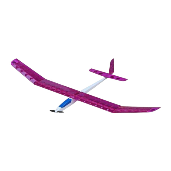
# 15523
Amethyst III
Wingspan 1260mm
R/C flight model for electric drives for control via 3 channels (rudder, elevator, motor)
MADE IN GERMANY
English Instructions
are available for download. Please check the product page on our website
Instructions en français
disponibles en téléchargement. Visitez notre site Internet.
disponibili per il download. Visita il nostro sito web.
Istruzioni in italiano
Advertisement

Related Manuals for Pichler Amethyst III


Summary of Contents for Pichler Amethyst III
- Page 1 Manual # 15523 Amethyst III Wingspan 1260mm R/C flight model for electric drives for control via 3 channels (rudder, elevator, motor) MADE IN GERMANY English Instructions are available for download. Please check the product page on our website Instructions en français disponibles en téléchargement.
- Page 2 Please check the corresponding product page at our online shop www.pichler-modellbau.de to see if there is a newer version of this manual or if there are any additions. The kit is intended for advanced model builders who have experience in building model aircraft. The model was developed especially for electric drives and is not suitable for combustion engines.
- Page 3 To build the model, a straight board such as the Extron Building Board 300×1200mm # X5537 is required as a building base. Protect the base with foil to prevent the parts from sticking to the base. Fuselage construction The following components are required first: A1 - A2, B1 - B9 as well as C1 - C3, C6 and C8. Carefully hammer the M4 drive-in nut into the servo board C8.
- Page 4 Glue the fuselage formers C1 and C2 and the servo board C8 as shown. Glue in the second fuselage side panel A1.
- Page 5 Glue in fuselage formers C3 and C6. Glue in reinforcing strips A2 and cover B4.
- Page 6 Glue the front upper fuselage planking from parts B6 and B7. File part B6 approx. 5mm wide in the center so that the flap of the canopy can be inserted later. Then glue the part to the front top of the fuselage. Adjust the two upper planking panels B9 as shown, shorten them accordingly and glue them as shown.
- Page 7 Glue lower fuselage planking B2 and B3.
- Page 8 Sand off protruding edges on the canopy and match the front fuselage sides to the motor bulkhead. Tip We recommend starting sanding with 180 grit sandpaper, fine sanding with 240 grit. Glue on front planking parts B7 and B8.
- Page 9 Sand the front part of the fuselage flat and glue the ring G2 in the center of the front part. Then sand the front part of the fuselage.
- Page 10 Carefully separate the canopy from the fuselage using a sharp knife. Glue canopy guides G5 to the inside of both fuselage sides as shown. Glue plywood tab G4 into the canopy as shown. File part B6 slightly in the center from below so that the canopy tab can be inserted.
- Page 11 Fix and glue rear upper fuselage section with tape as shown. Route the bowden cable tubes in the fuselage and allow them to protrude slightly at the exits. Once the bowden cables have been fixed with glue, the rear fuselage bottom section can be glued and secured with tape until cured.
- Page 12 Adjust the tailplane support C7 as shown. We recommend to glue this part only at the end, when all parts of the model are already covered with foil. Construction of elevator and rudder Glue the elevator parts F1 - F2 as shown. Sand the elevator at an angle of approx.
- Page 13 Then fit the rudder horn. We recommend gluing the rudder horn only at the end, after all parts have been finished covering. The finished elevator before fine sanding. This illustration shows the components of the rudderF4 - F8.
- Page 14 Glue the parts of the rudder as shown and fit the rudder horn C9. We recommend gluing the rudder horn only at the end, after all parts have been completed. Assembly diagram of the rudder and elevator.
- Page 15 Wings construction First, carefully remove the ribs D1 (18 pieces). Carefully smooth the straight undersides of the ribs with a sanding block (180 grit) so that they will later lie exactly on the building board. Glue ribbed strip D8 butt to each other.
- Page 16 Then glue the ribbed strip flush to the wing end strip (long triangular strip). The EXTRON building board with line grid and the EXTRON push pins provide valuable services here. Carefully smooth the undersides of the E1 rib comb with a sanding block (180 grit).
- Page 17 Glue the two parts of the rib comb together. Secure the wing end strip to the building board with push pins.
- Page 18 The pine strip is arranged lying flat on the building board.The rib comb E1 "stands" vertically in the wing ribs. We start the alignment by placing the penultimate rib in each case.
- Page 19 After all the ribs are threaded, you can start gluing. The last rib on the left and right must be glued in at a slight angle (use template F9 for alignment) so that the wing later achieves the correct V-shape.
- Page 20 Now the Ø 4mm round bar (leading edge) can be glued in place. Now glue the upper pine strip to the rib comb. The center wing section is now complete. Next, we turn to building the outer wings with edge arches. Pin the wing end strip (triangular strip) and the A3 edge sheet to the building board as shown.
- Page 21 Then glue the ribbed strip flush to the wing end strip (long triangular strip). For the construction of the outer wings we need the ribs D2 - D6. Attention - These must of course be built up laterally reversed 1x for left side and 1x for right side. Lay the pine strip flat on the building board and insert the rib comb D7 vertically.
- Page 22 Now the Ø 4mm round bar (leading edge) can be glued in place. Now glue the upper pine strip to the rib comb. Finally, sand all wing parts clean.
- Page 23 The three wing panels are now butt glued together. The height of the dihedral should be about 110mm on each side as shown. Our Mini Clamps C4923 work perfect during bonding.
- Page 24 The wing attachment C4 is now glued in place. The transom C5 can be glued in place after the model has been covered.
- Page 25 The G3 reinforcement plate for the fixing screw is glued on centrally. The recommended motor is fastened with 4 screws. Make sure that the cables do not drag on the motor, if necessary, some wood must be removed at the appropriate place inside the fuselage.
- Page 26 The G1 cabin bolt is fixed with a screw. Here the installation position of the servos and the linkages is shown.
- Page 27 Our liability is limited to the value of the model kit. Since we cannot supervise the proper assembly and operation of the model aircraft, we do not assume any liability for consequential damages. spare parts Spare parts are available for the Amethyst III. Further information is available at www.pichler-modellbau.de or in the Online Shop. Questions, suggestions & technical support...
-
Page 28: Important Note
IMPORTANT NOTE Please check the corresponding product page in our online store to see if a newer version of this manual or supplements to it are available. © Pichler Modellbau, August 2022 Version 1.1 Subject to changes Stay in touch with us! Follow us on Facebook, YouTube and Instagram Mit Smartphone und QR - Code direkt zu unseren Kanälen:...
Need help?
Do you have a question about the Amethyst III and is the answer not in the manual?
Questions and answers
My glider is a pichler charisma electric how is the tail connected and fixed on to the fuselage by the photo is how it is now I doesn’t look right can you help me
The tail of the Pichler Charisma Electric glider is connected and fixed to the fuselage as follows:
1. The tailplane support part C7 is adjusted but not glued until all parts of the model are covered with foil.
2. Elevator parts F1 and F2 are glued together, and one side is sanded at a 45° angle.
3. The rudder is assembled using parts F4 to F8.
4. The rudder horn C9 is fitted but recommended to be glued only after covering is complete.
5. Once the bowden cable tubes are routed and glued inside the fuselage, the rear fuselage bottom section is glued and secured with tape until the glue cures.
This ensures proper alignment and secure attachment of the tail components to the fuselage.
This answer is automatically generated
on the picker charisma how is the tail fixed onto the end of the fuselage that by the photo is how iv got it now
The transom C5, which is part of the tail assembly, is glued in place after the model has been covered.
This answer is automatically generated