Advertisement
Quick Links
Manual
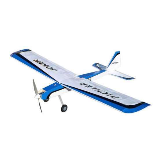
Joker
# 15382
Wingspan 1550mm
R/C flight model for electric drives
Control via 4 channels (rudder, elevator, aileron, motor)
MADE IN GERMANY
are available for download. Please check the product page on our website
English Instructions
disponibles en téléchargement. Visitez notre site Internet.
Instructions en français
Istruzioni in italiano
disponibili per il download. Visita il nostro sito web.
Advertisement

Related Manuals for Pichler Joker 15382


Summary of Contents for Pichler Joker 15382
- Page 1 Manual Joker # 15382 Wingspan 1550mm R/C flight model for electric drives Control via 4 channels (rudder, elevator, aileron, motor) MADE IN GERMANY are available for download. Please check the product page on our website English Instructions disponibles en téléchargement. Visitez notre site Internet. Instructions en français Istruzioni in italiano disponibili per il download.
- Page 2 Read these assembly instructions completely before you start building. Familiarize yourself with the basic construction. Please check the corresponding product page in our online shop at www.pichler.de to see if there is a newer version of these instructions or additions.
- Page 3 Building the wing Place the wing spar B1 and insert the ribs from left to right: A6, A5 (3x), A4 (2x), A3, A2, A1. Insert servo ATTENTION The wing is made in two parts so that it board D2. Do NOT glue yet. Use a 1.7mm thick balsa can be disassembled for transport.
- Page 4 Fit strip G1 onto the ribs at the front. Attach strip G2 to the ribs at the rear. Align wing components and then glue them in place.
- Page 5 Glue upper bar B2. Glue in servo board D2. Sand strip G1 / G2 to match the ribs.
- Page 6 Glue in edge curve D3. Cut excess planking to length as shown. To glue on the bottom planking, coat the ribbed framework with white glue in the appropriate places. Place the planking section flat on the Sand wing flush at front. building board Place the rib frame on the planking section and align.
- Page 7 Glue on the top planking as well. Fix while drying. If necessary, sand the front wing flush again and glue Cut planking pieces from 1.7mm thick balsa boards with a length to cover the first 3 ribs A1 to A3. on the strip H1.
- Page 8 Sand flush as shown. Glue the lower planking parts first. Now glue the upper planking made of 1.7mm balsa board.Sand any excess planking flush with the ribs. Glue in filler pieces H3 as shown as reinforcement. Fit in the brass tube.
- Page 9 Glue in brass tube with 3mm overhang. Do NOT glue Grind the leading edge and end strip. in end rib A7 yet. Glue on small piece of plywood from scrap material as shown as stopper for surface connecting rod. Grind the top and bottom of the end strip so that it tapers towards the end of the edge curve, as dictated by the slope on the spar.
- Page 10 Glue on the A7 closing rib. Cut the triangular strip for the ailerons to 730mm and adjust it at the end to the course of the end strip. (sand) If a foil hinge is used, grind the lower edge to approx. 30 degrees.
- Page 11 Glue together the motor bulkhead from parts F1. Carefully drive in the drive-in nut. Building the fuselage Glue side parts C1 and D1 together. Glue parts B6 together. Glue on reinforcements B3.
- Page 12 Glue servo board, B8 and C5 in place. The pin of B8 Carefully drive in the drive-in nuts. must point downwards, this will later engage with the bottom of the fuselage. When gluing C5, the longer side (63 mm) must be (63 mm) to the rear towards B8 and the shorter side (62 mm) must point forward to the motor bulkhead.
- Page 13 Glue the fuselage halves together and fix them. Glue part C6 in the fuselage. Glue the magnets into the service flap C2. Glue in part B5. Make sure that they are inserted in the correct position and do not repel the magnets in C6. Glue magnets into part C6.
- Page 14 Glue fuselage bottom part E2 and part B4. Glue reinforcement F2 to front fuselage bottom C3. Carefully drive in the drive-in nuts. Glue in upper fuselage section E1. Glue in front fuselage bottom C3.
- Page 15 Glue the fin from J1 to J7. Sand after drying. Glue the rudder from K1 to K6. Building the elevators Glue the elevator from parts I1 to I8.
- Page 16 Grind the rudder to a 45° angle at the leading edge Mounting the landing gear for flow hinge. Sand the front edge of the elevator at an angle when Attach main landing gear with two screws from using foil hinges. below.
- Page 17 Bend the undercarriage wire with pliers as shown. Mount star wheel with adjusting ring. The 10mm grid on the building board shows the bending dimensions. The rear landing gear is attached with two screws.
- Page 18 Center drill the rudder so that the angled landing R/C Installation gear wire can be inserted. The servos are screwed into the existing openings in the fuselage and wings. The wing servos are directly hinged with steel wire. Elevator and rudder are hinged by push rods which are to be made as follows: Bend the free end of the threaded rod by 90°.
- Page 19 No. X9983, to prevent scratching of the foil during ironing. The flight battery can be securely fastened to the battery board using Pichler Velcro straps, Order.No. C4738. The optimum center of gravity of the model can be adjusted by moving the flight battery.
- Page 20 For spare parts inquiries, general questions and suggestions please write us an eMail to service@pichler.de We wish you a lot of flying fun as well as spar and rib breakage! © Pichler Modellbau, September 2023 Building instruction version V1.0...
Need help?
Do you have a question about the Joker 15382 and is the answer not in the manual?
Questions and answers