Table of Contents
Advertisement
Quick Links
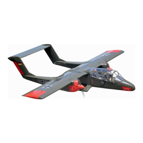
OV-10 BRONCO
Technische Daten
- Spannweite = 1800 mm
- Länge = 1280mm
- Gewicht = ca. 6900g
- Flächeninhalt = 57.1dm
- Flächenbelastung = 119.1 g/dm
- Flächenprofil = Naca Airfoil
Empfohlener E-Antrieb
- Brushless Antriebsset BOOST 45
- LiPo Akku LEMONRC 4300-3S
2
2
Instruction Manual book
Specifications
- Wingspan = 1800 mm
- Length= 1280mm
- Weight = approx. 6900g
- Wing Area = 57.1dm
- Wing Loading = 119.1 g/dm
- Airfoil = Naca Airfoil
Power Set (recommended)
- Brushless Power Set BOOST 45
- LiPo Battery LEMONRC 4300-3S
Montageanleitung
2
2
Advertisement
Table of Contents

Related Manuals for Pichler OV-10 BRONCO


Summary of Contents for Pichler OV-10 BRONCO
-
Page 1: Technische Daten
Montageanleitung Instruction Manual book OV-10 BRONCO Technische Daten Specifications - Spannweite = 1800 mm - Wingspan = 1800 mm - Länge = 1280mm - Length= 1280mm - Gewicht = ca. 6900g - Weight = approx. 6900g - Flächeninhalt = 57.1dm - Wing Area = 57.1dm... -
Page 2: Table Of Contents
Assembly Take particular care here. sides the same way. (in this case twice). Set all scerws securely. If they come off during Warning! flight you will lose control of your aircraft! Page 2 Instruction Manual Book OV-10 BRONCO... - Page 3 Sonderzubehör für OV-10 Bronco / Accessories for OV-10 Bronco Nachstehendes Zubehör wurde von uns ausgiebig erprobt und wird für beste Flugeigenschaften empfohlen. Weitere Informationen und Bestellmöglichkeit unter www.pichler-modellbau.de These accessories have been extensively tested and are recommended for best flying performance.
-
Page 4: Parts Listing (Not Included)
Place the servo into the servo tray. Center the 6. Repeat step # 2 - # 5 to install the second aileron servo within the tray and drill 1.5mm pilot holes servo in the opposite wing half. Page 4 Instruction Manual Book OV-10 BRONCO... - Page 5 For Flap. For Flap. 1.5mm For Aileron. For Aileron. Screw 1.5mm 1.5mm 2 x 10mm Screw For Aileron. Warning! - - - - 16 2x10mm Tie the string. Pull out servo cord with string. Instruction Manual Book OV-10 BRONCO Page 5...
-
Page 6: Installing The Control Horns And Linkages
The servo arm should be perpendicular to connect both of the aileron servo leads using a Y- the servo and point toward the middle of the wing. harness you have purchased separately. Page 6 Instruction Manual Book OV-10 BRONCO... - Page 7 Silicone tube Mark the spot to attach Bend 90 Silicone Tube 2mm Nut Push rod Push rod Flaslink Servo arm Bottom view Instruction Manual Book OV-10 BRONCO Page 7...
-
Page 8: Installing The Engine Mount
9) Secure the fuel tank. tank, the top of the vent tube should rest just below the top surface of the tank. It should not touch the top of the tank. Fuel tank Foam ring Silicone tube Page 8 Instruction Manual Book OV-10 BRONCO... -
Page 9: Installing The Engine
- - - - - - - 8 Engine to the engine mount using the screws provided. mount Flat w asher - - - - - - - 8 4mm Spring Washer - - - - - - - 8 Instruction Manual Book OV-10 BRONCO Page 9... - Page 10 Flat w asher 3x25mm 3mm Nut Flat w asher 4mm Spring 4x25mm Secure Secure 125mm Pushrod wire Page 10 Instruction Manual Book OV-10 BRONCO...
-
Page 11: Installing The Throttle
4x4mm Adjust throttle input 2x10mm (transmitter throttle stick), throttle trim movement and the Linkage stopper carburattor opening suitable position and screw in Pushrod wire approx.16mm the 4x4mm set screw. Screw Throttle servo Instruction Manual Book OV-10 BRONCO Page 11... -
Page 12: Installing The Electric Motor (Ep Version)
- - - - - 8 4mm Spring Washer - - - - - 8 3x15mm 3mm Spring Washer - - - - - 8 3mm Spring 10x40mm 4x60mm 4mm Spring 4mm Washer 4mm Washer Page 12 Instruction Manual Book OV-10 BRONCO... -
Page 13: Rudder Installation
(see page 6, 7). Control horn and linkages for Rudder are installed the same way as the aileron before (see page 8, 9). Rudder pushrod Rudder servo Horn Instruction Manual Book OV-10 BRONCO Page 13... -
Page 14: Installing Horizontal Stabilizer
Hinges and servo for Elevator are glued the same way as the aileron before (see page 6, 7). Control horn and linkages for Elevator are installed the same way as the aileron before (see page 8, 9). 2x10mm Page 14 Instruction Manual Book OV-10 BRONCO... -
Page 15: Installing The Wheel Well
INSTALLING THE WHEEL WELL Using a modeling knife, carefully remove the film covering from the uselage gear tray. Make sure that you do not remove any wood. Cut the plastic Cut the plastic Instruction Manual Book OV-10 BRONCO Page 15... - Page 16 45mm Aluminium - - - - 2 45mm Aluminium Page 16 Instruction Manual Book OV-10 BRONCO...
-
Page 17: Installing Main Gear
5.1mm hold 3x6mm Button Screw 5.1mm hold 3mm Nut - - - - - - 2 - - - - - - - - 1 5x30mm 5mm Washer 4x4mm Nose gear Main gear Instruction Manual Book OV-10 BRONCO Page 17... - Page 18 THERE ARE TWO OPTIONS: OPTION 1: MAIN GEAR STRUTS 3x15mm Screw 2.5mm Screw the gear in position Screw Page 18 Instruction Manual Book OV-10 BRONCO...
-
Page 19: Electric Gear Retracts
OPTION 2: ELECTRIC GEAR RETRACTS Screw 2.5mm Screw the gear in position Screw Instruction Manual Book OV-10 BRONCO Page 19... -
Page 20: Installing The Nose Gear
INSTALLING THE NOSE GEAR OPTION 1: NOSE GEAR STRUT Crimp Cable rod Screw Page 20 Instruction Manual Book OV-10 BRONCO... - Page 21 Screw the gear in position 3x15mm 2.5mm Screw OPTION 2: ELECTRIC GEAR RETRACTS 3x6mm Spring Screw Instruction Manual Book OV-10 BRONCO Page 21...
- Page 22 Screw the gear in position Crimp Cable rod 3x15mm Screw 3x6 mm Screw 2.5mm Screw the gear in position Screw Page 22 Instruction Manual Book OV-10 BRONCO...
- Page 23 Cab link approx.16mm Servo nose gear Servo nose gear Instruction Manual Book OV-10 BRONCO Page 23...
-
Page 24: Mounting The Cowl
7) Install the muffler. Connect the fuel and pressure of masking tape. lines to the carburator, muffler and fuel filler valve. Tighten the screws completely. 3 x 12mm Screw - - - - 12 3x12mm Screw 15mm Page 24 Instruction Manual Book OV-10 BRONCO... - Page 25 6 x 45mm - - - 2 Antenna Antenna 6 x 45mm Page 25 Instruction Manual Book OV-10 BRONCO...
-
Page 26: Installing The Spinner
If it dose, use a sharp modeling knife and carefully trim away the spinner cone where the propeller comes in contact with it. - - - - 2 Warning! 3x15mm- - 4 Instruction Manual Book OV-10 BRONCO Page 26... - Page 27 3x15mmScrew Instruction Manual Book OV-10 BRONCO Page 27...
-
Page 28: Plastic Parts For Fuselage
Do not permanently secure the receiver and 3) Secure the switch in place using the two battery until after balancing the model. machine screws provided with the radio system. Page 28 Instruction Manual Book OV-10 BRONCO... -
Page 29: Wing Attachment, Horizontal Stabilizer
Zip tie Switch Receiver Switch Battery for Receiver Fuselage top side Zip tie Battery for Motor WING ATTACHMENT, HORIZONTAL STABILIZER . 19mm Aluminium tube. 544mm 384mm Fuselage top side Instruction Manual Book OV-10 BRONCO Page 29... - Page 30 - - - 2 4x20mm Screw horizontal stabilizer in position. 4x20mm 4x20mm Screw 4x20mm Screw Fuselage top side 4x15mm Attach the wings to the joiner tube and secure the wing panels to the fuselage. 4x15mm Page 30 Instruction Manual Book OV-10 BRONCO...
-
Page 31: Installing Cockpit Fuselage
Use canopy glue to secure the canopy to the canopy hatch. Use low-tack tape to hold the canopy in position until the glue fully cures. Wrap the tape completely around the canopy hatch. Instruction Manual Book OV-10 BRONCO Page 31... - Page 32 Open/Close Page 32 Instruction Manual Book OV-10 BRONCO...
-
Page 33: Balancing
85mm back from the leading edge, at the firewall. When balanced correctly, the airplane should sit level or slightly nose down when you lift it up with your fingers. 85 mm Schwerpunkt Instruction Manual Book OV-10 BRONCO Page 33... -
Page 34: Lateral Balance
14 mm down — Rudder: 25 mm right 25 mm left — Flap: 20 mm down Ruderausschläge 12mm Querruder 12mm Aileron control 14mm Höhenruder 14mm Elevator 25mm Seitenruder 25mm Rudder control Landeklappen 20mm Flap control Page 34 Instruction Manual Book OV-10 BRONCO... -
Page 35: For Your Radio Installation Basic Connection For Airplane And Adjustment Of Servos
(only one ESC) Take the red line out the BEC connector, and then insulate it with a bit of electrical tape for futher use. Motor Receiver Instruction Manual Book OV-10 BRONCO Page 35... -
Page 36: Main Gear Dimensional Detail
MAIN GEAR DIMENSIONAL DETAIL NOSE GEAR STRUTS LANDING GEAR MOUNT. MAIN GEAR STRUTS 31mm 41mm 44mm 5.1mm hold 5.1mm hold 25mm 21mm Page 36 Instruction Manual Book OV-10 BRONCO...
Need help?
Do you have a question about the OV-10 BRONCO and is the answer not in the manual?
Questions and answers