FIOR & GENTZ NEURO HiSWING R+ Instructions For Use Manual
System ankle joint
Hide thumbs
Also See for NEURO HiSWING R+:
- Instructions for use for patients (30 pages) ,
- Maintenance manual (19 pages)

Related Manuals for FIOR & GENTZ NEURO HiSWING R+


Summary of Contents for FIOR & GENTZ NEURO HiSWING R+
- Page 1 Instructions for Use for Qualified Specialists in Orthopaedic Technology System Ankle Joint NEURO HiSWING R+ Download: www.fior-gentz.com...
-
Page 2: Table Of Contents
Content Page Instructions for Use for Qualified Specialists in Orthopaedic Technology System Ankle Joint NEURO HiSWING Information Safety Instructions Classification of the Safety Instructions All Instructions for a Safe Handling of the System Ankle Joint Intended Use Indication Contraindication Qualification Application Combination Possibilities with Other System Joints Joint Functions Modes... - Page 3 15.2.3 Cable Connection Test 15.2.4 Settings 15.2.4.1 Calibrate 15.2.4.2 Sound 15.2.4.3 Mode Change 15.2.4.4 Restore 15.2.4.5 Basic Position 15.2.4.6 Gestures 15.2.4.7 Angle for Stair Mode 15.2.5 Step Counter 15.2.6 Controller Update 16. Advice on Optimal Orthosis Functionality 16.1 Bluetooth® Connection 16.2 System Ankle Joint 16.3...
-
Page 4: Instructions For Use For Qualified Specialists In Orthopaedic Technology System Ankle Joint Neuro Hiswing R
Instructions for Use for Qualified Specialists in Orthopaedic Technology System Ankle Joint NEU- RO HiSWING R+ Information These instructions for use are addressed to qualified specialists in orthopaedic technology and do not contain any notes about dangers which are obvious to them. To achieve maximum safety, please instruct the patient and/or care team in the use and maintenance of the product. - Page 5 WARNING Risk of Falling Due to Permanent Higher Load If patient data has changed (e.g. due to weight gain, growth or increased activity), recalculate the ex pected load on the system joint, plan the treatment again and, if necessary, produce a new orthosis. WARNING Risk of Falling Due to Improper Heel Height Determine with the patient a maximum heel height of the shoes to be worn with the orthosis.
- Page 6 WARNING Risk of Falling Due to Electromagnetic Interference Do not use the ankle joint system in close proximity to or stacked with other portable RF communication devices in order to avoid impairing the function of the ankle joint system. If such use is necessary, observe the ankle joint system and other portable RF communication devices in use to ensure that they function normally.
- Page 7 WARNING Risk of Injury Due to Improper Handling of the Controller Use the controller as described in these instructions for use. The controller is a sensitive electronic device with an integrated lithium-polymer battery. Pay particular attention to: - not wearing the orthosis during the battery charging process, - avoiding contact with strong heat or fire, - not charging the controller under direct sunlight, and - not opening the controller.
-
Page 8: Use
Intended Use The NEURO HiSWING R+ ankle joint system with component set, including system ankle joint and controller, is exclusively for use for orthotic fittings of the lower extremity. The system joint is only allowed to be used for producing an AFO or a KAFO. Every system joint influences the orthosis’ function and thus also the function of the leg. -
Page 9: Joint Functions
Joint Functions The NEURO HiSWING R+ is a microprocessor-controlled, automatic system ankle joint and provides the following joint functions: - Zero mode for resetting the lower leg-to-plumb line angle to the basic position, e.g. for walking uphill and downhill - Relax mode for situations in which the patient wants to use the orthosis as a free moving orthosis, e.g. to relax the foot while sitting - Stair mode for adjusting the lower leg-to-plumb line angle when climbing stairs - alternative function with control button for situations in which the ankle joint angle needs to be adjusted... -
Page 10: Modes
Modes The automatic ankle joint system is equipped with the Zero, Relax and Stair mode. If none of these modes is active, the controller is in standby and ready for a possible activation of a mode. The system joint can then be used normally and improves the patient's stability while walking and standing with the help of the spring units used. -
Page 11: Relax Mode
4.1.2 Relax Mode In Relax mode, the system ankle joint is free moving and the patient can freely adjust the lower leg-to-plumb line angle to relax the foot while sitting. If the automatic system ankle joint has been combined with an automatic system knee joint, Relax mode is not available. -
Page 12: Neuro Hiswing R+ Ankle Joint System
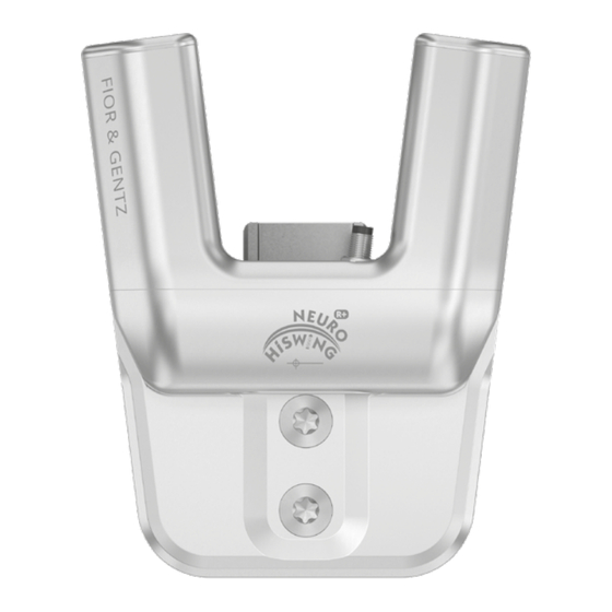
NEURO HiSWING R+ Ankle Joint System The ankle joint system is equipped with Bluetooth® technology* and consists of the following components (fig. 3): system ankle joint controller charging cable with adapter and User app for the patient Expert app for qualified specialists in orthopaedic technology The system ankle joint and the controller are built into the patient's orthosis. - Page 13 In order to produce an orthosis with the NEURO HiSWING R+, you need a controller set and a connection cable set in addition to the system ankle joint. Even if you want to combine the system ankle joint with an automatic system knee joint from the FIOR & GENTZ product range in a KAFO, you only need one controller.
-
Page 14: Scope Of Delivery Of The System Ankle Joint
Connection Cable Set NEURO HiSWING R+, NEURO HiTRONIC (SL3860-K/4) Quantity Item Article Number Description Unit Unilateral connection cable for functional unit NEURO HiTRONIC w/o fig. ET0713-02 pce. and NEURO HiSWING R+, 660mm lamination dummy for connection cable for functional w/o fig. ET0972-3 pce. -
Page 15: Load
Load The actual load on the system joints is based on the relevant patient data and the choice of shoes. When selecting the system joint, the maximum heel height of the shoes that the patient wants to wear with the orthosis must be taken into account after consultation with the patient. -
Page 16: Demounting The Functional Unit
10.1 Demounting the Functional Unit 1 Unscrew both countersunk flat head screws. 2 Screw the pressing screw into the thread of the first screw (S1, fig. 15). The pressing screw must not be screwed in completely (fig. 11). 3 Push the joint's upper part and the functional unit apart by exerting force on them fig. -
Page 17: Checking The System Joint's Free Movement
5 Screw in the second countersunk flat head screw (axle screw, S2; fig. 19). 10.4 Checking the System Joint's Free Movement Tighten the screws for the functional unit with the appropriate torque (see para- graph 10.7). Check if the system joint moves freely. If the system joint runs with lateral play, mount the next thicker sliding washer. -
Page 18: Checking The Control Button
10.6 Checking the Control Button After mounting the spring units, check the function of the control button. 1 Press and hold the control button. 2 Move the system joint in ap direction and check if the ankle joint angle can be changed. 3 Release the control button and check if the new ankle joint angle is secured and remains in place. -
Page 19: Setting Or Adjusting The Orthosis Alignment
11.1 Setting or Adjusting the Orthosis Alignment With the app, the lower leg-to-plumb line angle can be continuously adjusted by up to 17° in both directions. Alternatively, the control button on the system joint can also be used for this purpose. Make all adjustments to the orthosis on the workbench and not on the patient’s leg. -
Page 20: Reading The Joint Angles
11.4 Reading the Joint Angles There are markings (fig. 29) on all system ankle joints and system stirrups which indicate the angle of the system components to each other. This allows you to check the individual normal posture (the orthosis' basic alignment), record the joint angle and compare later deviations. -
Page 21: Controller
13. Controller The controller is delivered with the component set and is mounted onto the orthosis. It receives adjustments from the Expert app and commands from the User app, registers the patient’s movements and controls the NEURO HiSWING R+ system ankle joint. When producing the orthosis, ensure that the controller is positioned so that the charging port is at the bottom. -
Page 22: Manual Mode Change
13.2 Manual Mode Change A MODE button is built into the controller, which can be used to change the mode of the orthosis without the app. Depending on the mode that is already selected, it can be switched in the following order by pressing briefly: Zero, Relax and standby. -
Page 23: Adjustment Options With The Expert App
15. Adjustment Options with the Expert App 15.1 Selecting a Mode The available modes (Zero, Relax and Stair mode) can be selected using the app. Zero mode can additionally be activated using gestures (see paragraph 15.2.4.6). You will find further information in the app. 15.2 Main Menu In the main menu you can set various adjustments for the orthosis. -
Page 24: Mode Change
15.2.4.3 Mode Change With this menu item you can adapt the sensitivity of the controller for a mode change, in order to enable a mode change via app even when in motion. Usually, the patient changes the mode while at standstill. Chang- ing the mode while the patient is in motion can endanger the patient's safety. -
Page 25: Controller Update
15.2.6 Controller Update When updating the app, the controller update is downloaded at the same time, if available. In the app, you can update the desired controller by following the instructions in the app. Always keep all controllers in use up to date. The ankle joint system must not be actively used during the update. -
Page 26: Maintenance
17. Maintenance Check the system joint regularly for wear and functionality. In particular, check the joint components listed in the following table for the possible problems described and, if necessary, take the appropriate measures. Also check the functionality after every maintenance carried out. It must be possible to move the system joint without problems or unusual noises. -
Page 27: Documentation Of Maintenance In The Orthosis Service Passport
every 6 every 48 system stirrup wear or breakage replacing system stirrup months months every 6 connection cable damage replacing connection cable if required months software for mobile devices (operating security gaps in the every 6 updating software if required system, Expert app, software months... -
Page 28: Functional Check Of The Ankle Joint System
17.3 Functional Check of the Ankle Joint System In order to check the function of the ankle joint system, proceed as follows: 1 Check whether the system joint can be moved in Relax mode without any restrictions or unusual noises. 2 Check whether the settings are retained when the controller is in standby and the system joint is loaded in both directions. -
Page 29: Period Of Use
18. Period of Use To guarantee a safe use and complete functionality as well as an unlimited period of use of the system joints, you must adhere to the following conditions: - Adhere to the specified maintenance intervals without interruption and document each maintenance (see paragraph 17). -
Page 30: Spare Parts
20. Spare Parts 20.1 Exploded View Drawing NEURO HiSWING R+ The functional unit is delivered preassembled. If individual components of the functional unit (fig. 39) have to be exchanged, you can order them as well. fig. 39 All system stirrups of the NEURO HiSWING R+ system ankle joint are delivered with an integrated sliding bushing. -
Page 31: Spare Parts For The Neuro Hiswing R+ System Ankle Joint
20.2 Spare Parts for the NEURO HiSWING R+ System Ankle Joint Article Number for System Width Item 20mm Description SB1069-L0960 bearing nut SH0815-TI upper part, straight, titanium SH0835-TI upper part, bent inwards, titanium SH0835-8/TI upper part, bent outwards, titanium GS2611-* sliding washer* SH0865-2/L spring unit cover, left lateral or right medial... -
Page 32: Sliding Washers
20.4 Sliding Washers * Sliding Washers Article Number for System Width 20mm Ø = 24mm GS2611-040 GS2611-045 GS2611-050 GS2611-055 GS2611-060 21. Disposal Dispose of the system joint and its individual parts properly. The hydraulic oil con- tained in the functional unit must be disposed of through the appropriate collection points, observing the local regulations for the disposal of waste oil. -
Page 33: Technical Data
22. Technical Data NEURO HiSWING R+ period of use unlimited, excluding wear parts (see paragraph 17) protection type IP44 operating mode continuous operation 22.1 Ambient Conditions Operation -10°C – +40°C ambient temperature +5°C – +40°C when charging the battery, no exposure to direct sunlight relative air humidity 0% –... - Page 34 Adapter with Charging Cable (not Part of the Medical Device) article number ET0780-01 manufacturer’s designation FW8002.1MUSB/05 ambient temperature in operation 0°C – +45°C ambient temperature in storage -40°C – +70°C relative air humidity 10% – 90%rH input voltage 100V – 240V input frequency 50Hz –...
-
Page 35: Signs And Symbols
23. Signs and Symbols CE labelling according to Regulation (EU) 2017/745 for medical devices medical device article number Do not dispose of electronic devices with household waste. Dispose of the device and accessories at official delivery points for electronic devices. manufacturer batch code serial number... -
Page 36: Ce Conformity
follow the instructions for use (white on blue background) single patient – multiple uses IP44 protection from the ingress of solid foreign bodies (diameter ≥ 1.0mm) and from splashing water on all sides Unique Device Identifier – product identification number Controller Type Plate Input: 5V/1A, Type: FW8002.1MUSB/05... -
Page 37: Electromagnetic Compatibility
All copy rights, particularly the distribution, copy and translation of these instructions for use or any part of it, must be authorised by FIOR & GENTZ Gesellschaft für Entwicklung und Vertrieb von orthopädietechnischen Systemen mbH. Reprints, copies and any other electronic reproduction, even partial, must be authorised in writing by FIOR &... -
Page 38: Electromagnetic Immunity For All Devices And Systems
26.3 Electromagnetic Immunity for all Devices and Systems Usage Instructions and Manufacturer’s Declaration – Electromagnetic Immunity The product NEURO HiSWING R+ is designed for operation in an electromagnetic environment as specified below. The customer or user of the product NEURO HiSWING R+ must ensure that it is operated exclusively in such an environment. -
Page 39: Electromagnetic Immunity For Non-Life-Supporting Devices And Systems
26.4 Electromagnetic Immunity for Non-Life-Supporting Devices and Systems Usage Instructions and Manufacturer’s Declaration – Electromagnetic Immunity The product NEURO HiSWING R+ is designed for operation in an electromagnetic environment as specified below. The customer or user of the product NEURO HiSWING R+ must ensure that it is operated exclusively in such an environment. -
Page 40: Recommended Safety Distances Between Portable And Mobile Rf Telecommunication Equipment And The Product Neuro Hiswing R+ For Non-Life-Supportingdevices And Systems
26.5 Recommended Safety Distances between Portable and Mobile RF Telecommunication Equipment and the Product NEURO HiSWING R+ for Non-Life-Supporting Devices and Systems Usage Instructions and Manufacturer’s Declaration – Recommended Safety Distances between Portable and Mobile RF Telecommunication Equipment and the Product NEURO HiSWING R+ The product NEURO HiSWING R+ is designed for operation in an electromagnetic environment where RF interference is monitored. -
Page 41: Test Specifications For The Immunity Of Enclosures Against Wireless Rf Telecommunication Equipment
26.6 Test Specifications for the Immunity of Enclosures Against Wireless RF Telecommunication Equipment Test Frequency Maximum Distance Immunity Test Frequency Band Radio Service Modulation Output Level [V/m] [MHz] [Mhz] pulse modula- 380 to 390 TETRA 400 tion 18Hz GMRS 460, 430 to 470 ±... -
Page 42: Usa: Fcc Regulatory Compliance Statement
26.7 USA: FCC Regulatory Compliance Statement This device complies with Part 15 of the FCC Rules. Operation is subject to the following two conditions: (1) This device may not cause harmful interference, and (2) this device must accept any interference received, including interference that may cause undesired operation. -
Page 43: Information For The Treatment Documentation
27. Information for the Treatment Documentation Add these instructions for use to your treatment documentation! Patient Data Name Address Postcode, City Home Telephone Telephone at Work Insurance Insurance No. Attending Physician Diagnosis... -
Page 44: Handing Over The Orthosis
28. Handing Over the Orthosis The qualified specialist in orthopaedic technology has also handed over the instructions for use for patients as well as the orthosis service passport to you as a patient, parent or care team. By means of these instructions for use, the functions and handling of the orthosis were explained to you in detail.
Need help?
Do you have a question about the NEURO HiSWING R+ and is the answer not in the manual?
Questions and answers