Advertisement
Available languages
Available languages
Quick Links
SICK AG
Erwin-Sick-Straße 1
DE-79183 Waldkirch
www.sick.com
EX-1311-2F-5V (Part no: 2139287)
Q U I C K S TA R T
1.
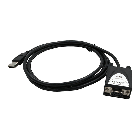
Product description
1
1. USB 2.0 A-connector for connection to computer
2. S1: 9-pin serial RS-232 female connector
The EX-1311-2F-5V is a converter for converting USB 2.0 to RS-232 interface
with FIFO 16C550 port for connecting high-speed serial RS-232 peripheral
devices (e.g. modem, plotter etc.). The EX-1311-2F-5V is equipped with a USB
2.0 A-connector for connection to the computer and an RS-232 serial 9-pin
female connector. Since the EX-1311-2F-5V has a 9-pin female connector, it is
therefore possible to connect the EX-1311-2F-5V directly to the end device. The
USB converter is hot plug & play capable. No jumpers or settings are required for
I/O address and interrupt settings, as the settings are automatically made by the
system BIOS during the installation of the operating system. The EX-1311-2F-5V
provides +5 V on pin 9.
Compatibility:
USB 1.1 & 2.0
Operating Systems: Windows 9.x / ME / 2000 / XP / Vista / 7 / 8.x / 10 / 11 /
Server 20xx / Linux / MAC
Connectors:
1x USB 2.0 A-connector, 1x 9-pin serial RS-232 female
connector
Product type:
EX-1311-2F-5V
2.
Connectors & status LEDs
RS-232 Pin assigments:
DB 9M
9 Pin serial female connector
Pin
1
5
1
2
3
6
9
4
5
RS-232 Cable wiring
DB9 (EX-1311-2F-5V)
1
DCD
2
RXD
3
TXD
4
DTR
5
GND
6
DSR
7
RTS
8
CTS
8029168//2024-01
2
Signal
Pin
Signal
DCD
6
DSR
RXD
7
RTS
TXD
8
CTS
DTR
9
+5V
GND
RS-232 (Device)
1
DCD
2
RXD
3
TXD
4
DTR
5
GND
6
DSR
7
RTS
8
CTS
USB 2.0 A-connector:
1 2 3 4
e n
Status LEDs:
1
1. RXD
2. TXD
3.
Hardware installation
Because there are large differences between computers, we only give a general
installation guide for the EX-1311-2F-5V. Please refer your computers reference
manual whenever in doubt.
1.
Connect the EX-1311-2F-5V USB to the USB A-port on your computer.
2.
If you would like to screw the serial cable to the 9-pin connector of the EX-
1311-2F-5V, unscrew the screws (see Fig. 1). Screw the supplied hexagon
nuts into the holes on the EX-1311-2F-5V (see Fig. 2). Now you can attach
the serial cable to the EX-1311-2F-5V.
Fig. 1: Remove the screws
3.
When ready, start the computer and continue with the driver installation.
4.
Driver installation
After the hardware installation, Windows will recognize the device automatically
and install the drivers. If the driver is not installed automatically, download the
driver from www.sick.com and open the folder "USB_to_IO/FTDI". Select the folder
with your operating system and install the driver. Follow the hardware assistant
and finish the installation.
Important! Restart your computer after installing the drivers.
Open the Device manager. You should see the following new entries under Ports
(COM & LPT) and USB-Controller:
If you see this or a similar information the device is installed correctly.
5.
Cleaning
For cleaning, use only a dry fluffless cloth and remove the dirt with gentle pres-
sure. In the area of the connectors, make sure that no fibers from the cloth
remains.
Attention! Never use a moist or wet cloth for cleaning!
USB 2.0 A-connector
Pin
Signal
Pin
1
VCC
3
2
DATA-
4
Fig. 2: Insert the hexagon nuts
EX-1311-2F-5V | SICK
Signal
DATA+
GND
2
Advertisement

Subscribe to Our Youtube Channel
Related Manuals for SICK EX-1311-2F-5V


Summary of Contents for SICK EX-1311-2F-5V
- Page 1 1311-2F-5V, unscrew the screws (see Fig. 1). Screw the supplied hexagon 2. S1: 9-pin serial RS-232 female connector nuts into the holes on the EX-1311-2F-5V (see Fig. 2). Now you can attach the serial cable to the EX-1311-2F-5V. The EX-1311-2F-5V is a converter for converting USB 2.0 to RS-232 interface with FIFO 16C550 port for connecting high-speed serial RS-232 peripheral devices (e.g.
- Page 2 RS-232 Peripherie Geräten (z.B. Modem, Plotter usw.). Der EX-1311-2F-5V ist mit einem USB 2.0 A-Stecker zum Anschluss an den Computer und einer RS-232 seriellen 9 Pin Dose ausgestattet. Da der EX-1311-2F-5V eine 9 Pin Dose hat, ist es somit möglich den EX-1311-2F-5V direkt an das Endgerät anzuschließen. Der USB Konverter ist Hot Plug und Play fähig.
Need help?
Do you have a question about the EX-1311-2F-5V and is the answer not in the manual?
Questions and answers