Advertisement
Advertisement
Table of Contents

Related Manuals for attika RAIS VISIO 3 Elements


Summary of Contents for attika RAIS VISIO 3 Elements
- Page 1 Installation instructions VISIO 3 Elements...
-
Page 2: Table Of Contents
1. Contents 1. Contents ............................ 2 2. Principle ............................ 2 3. General information ....................... 3-7 4. Parts list ............................ 8 5. Installation ........................... 9-14 6. Technical drawing ........................15 2. Principle All instructions provided with products must be followed. Damage occurring as a result of failure to follow these instructions is not covered by the guarantee, and no replacement parts can be claimed for such damage. -
Page 3: General Information
The installation and operating instructions must be adhered to. RAIS/Attika cannot be held liable for incorrect installation or irresponsible operation. - Page 4 RAIS A/S/Attika Feuer AG within the framework of the guarantee. Ordering spare parts: When requesting spare parts, mark the damaged area on the packing label enclosed and take a photo of the damage. Send the photo and packing label RAIS A/S/Attika Feuer AG.
- Page 5 Installation and operating instructions for the VISIO 3 fireplace insert tested according to DIN EN 13240 Installation details VISIO 3 is ready for connection, and must be fitted using a connection piece to the existing chimney. The connection piece must be as short as possible and run in a straight line, horizontal or slightly rising gradient.
- Page 6 Heating during seasonal changes When ambient temperatures are higher, a sudden temperature rise can affect chimney pressure, preventing full venting of combustion gases. In such instances, use less firewood and set the air damper higher to allow the firewood to burn faster (with flames), thus stabilising chimney pressure.
- Page 7 Spare parts Only use spare parts which have been expressly approved or supplied by the manufacturer. Please contact your dealer. Do not attempt to modify the fireplace! Information in the event of chimney fire Wood that is too damp or the wrong type can cause the build-up of deposits inside the chimney, which can result in a chimney fire.
-
Page 8: Parts List
4. Parts list Installation instructions for VISIO 3 Elements 13.06.2017... -
Page 9: Installation
5. Installation 1 Place the base plate of the CO-VIS03-08A on the floor at the installation site (see fig. 1) Fig. 1 2. Place VISIO 3 centered on the baseplate. The distance to the midline between the legs front and rear must be the same (155 mm). - Page 10 Fig. 2 Fig. 3 3. Cut the back wall of the CO-VIS03-020 and CO-VIS03-03A elements to size (e.g. with a grinder). The cuts should be made in slots. (See figs. 4 & 5) (See figs. 4 & 5) Fig. 4 Installation instructions for VISIO 3 Elements 13.06.2017...
- Page 11 Fig. 5 4. Place element CO-VIS03-03A on element CO-VIS03-020 and slide under the fireplace insert using the wooden rollers supplied (see figs. 6 and 7). Fig. 6 Installation instructions for VISIO 3 Elements 13.06.2017...
- Page 12 Fig. 7 5. Remove transport protection from the fireplace insert (see figs. 8 and 9). Refer to the installation instructions for the fireplace insert for information on removal of transport protection. Fig. 8 Installation instructions for VISIO 3 Elements 13.06.2017...
- Page 13 Fig. 9 6. Insert back wall plate CO-VIS03-03B and secure with acrylic adhesive (glue hardens within 10 minutes). Place element CO-VIS03-040 behind the fireplace insert (see fig. 10). CO-VIS03-040 CO-VIS03-03B Fig. 10 Installation instructions for VISIO 3 Elements 13.06.2017...
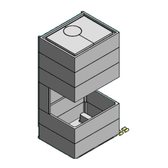
- Page 14 7. Glue the gaskets supplied onto element CO-VIS03-050 on the front between the element and the fireplace insert installation frame. One each, left and right under the element (see fig. 11). Lift element CO-VIS03-050 over the fireplace insert and position. Fig.
-
Page 15: Technical Drawing
6. Technical drawing Installation instructions for VISIO 3 Elements 13.06.2017...
Need help?
Do you have a question about the RAIS VISIO 3 Elements and is the answer not in the manual?
Questions and answers