Table of Contents
Advertisement
Quick Links
Advertisement
Table of Contents

Related Manuals for attika Rais 500


Summary of Contents for attika Rais 500
- Page 1 Rais 500 INSTALLATION MANUAL (UK)
- Page 2 PRODUCTION NUMBER SHALL BE STATED HERE 3 - EN...
-
Page 3: Table Of Contents
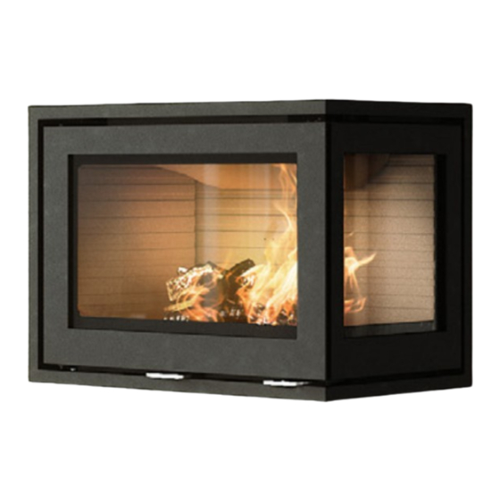
Rais 500-2 Right model - Glass version Rais 500-2 Right model - Classic version Rais 500-2 Left model - Glass version Rais 500-2 Left model - Classic version Rais 500-3 3 Side model - Glass version Rais 500-3 3 Side model - Classic version Revision: 21-02-2023 Date: We are not responsible for typographical errors. -
Page 4: Installation Instructions
Thank you for choosing your new RAIS or stated in the installation sections. When ATTIKA product. This installation instructions deciding where to install your RAIS/ATTIKA manual will ensure that your fireplace insert fireplace insert, you should think about being is installed correctly and that it will provide... -
Page 5: Technical Data
TECHNICAL DATA SPECIFICATIONS Danish Technological Institute ref.: 300-ELAB-2555-EN and 300-ELAB-2555-NS RAIS 500-1 RAIS 500-2 RAIS 500-3 FRONT MODEL RIGHT/LEFT MODEL 3 SIDE MODEL Nominal output (kW) Min./max. output (kW) 4–8* 4–8* 4–8* Heating area (m Fireplace insert width/depth/ 720 X 427 X 480... -
Page 6: Dimensional Sketches
DIMENSIONAL SKETCHES 500–1 427 ** 427 ** 427 ** 427 ** * AirSystem 17-0000-6550 ** Interior dimensions R500 Front model, Glass All dimensions are in mm. 22-02-2023 7 - EN... - Page 7 DIMENSIONAL SKETCHES 500-2 (right) 699 ** 339 ** 339 ** 339 ** 339 ** 427 ** 427 ** 427 ** 427 ** 339 ** 339 ** 699 ** 699 ** 699 ** 699 ** 427 ** 427 ** 427 ** 699 ** 699 ** * AirSystem...
- Page 8 DIMENSIONAL SKETCHES 699 ** 500-2 (left) 339 ** 339 ** 339 ** 339 ** 427 ** 427 ** 427 ** 339 ** 339 ** 699 ** 699 ** 699 ** 699 ** 699 ** 699 ** * AirSystem ** Interior dimensions All dimensions are in mm.
- Page 9 DIMENSIONAL SKETCHES 678** 500–3 339** 339** 339 ** 339** 339** 339 ** 339 ** 339** 339 ** n 147 n 147 n 147 n 147 339 ** 678** 678** 678** 678** 339** 339** 339** 339** * AirSystem ** Interior dimensions All dimensions are in mm.
-
Page 10: Production Number
PRODUCTION NUMBER The production number is located in the bottom left corner of the fireplace insert ( see drawing). It is also stated on the front of this installation manual. 11 - EN... -
Page 11: Information Plate
INFORMATION PLATE INFORMATION PLATE All RAIS/ATTIKA fireplace inserts have an information plate specifying the fireplace in- sert’s distance to flammable materials, efficiency etc. The information plate is laid loose in the fireplace insert upon delivery. See next page. EN - 12... - Page 12 EC.NO: 17 Notified Body: 1235 Produced at: RAIS A/S, Industrivej 20, 9900 Frederikshavn, Danmark Rais 500 Front model, Rais 500 Classic Front model AFSTAND TIL BRÆNDBART, BAGVÆG DK: mm SE BRUGERVEJLEDNING ABSTAND ZU BRENNBAREN BAUTEILEN, HINTEN DE: mm SIEHE BEDIENUNGSANLEITUNG...
- Page 13 RAIS A/S, Industrivej 20, 9900 Frederikshavn, Danmark Rais 500 Right model, Rais 500 Left model, Rais 500 3 Side model Rais 500 Classic Right model, Rais 500 Classic Left model, Rais 500 Classic 3 Side model AFSTAND TIL BRÆNDBART, BAGVÆG...
-
Page 14: Installation
INSTALLATION INSTALLATION The following section explains how to install the fireplace insert and includes informa- tion about the packaging, installation distances, etc. DELIVERY PACKAGING The fireplace insert is supplied secured to a transport pallet using four transport safe- ty fittings. The safety fittings are secured with screws, which must be unscrewed. The safety fitting can then be removed. -
Page 15: Choice Of Material For Installation
INSTALLATION CHOICE OF MATERIAL FOR INSTALLATION The material can be panels/brick with an insulation value greater than 0.03 m² x K/W. The insulation is defined as wall thickness (in metres) divided by the wall’s Lambda val- Contact your installation technician/chimney inspector. During testing, the fireplace insert is installed in a cabinet made from non-flammable 50 mm calcium silicate panels (Skamotec 225). -
Page 16: Installation Dimensions 500-1
INSTALLATION DIMENSIONS INSTALLATION DIMENSIONS: 500–1 Applies to installations made from non-flammable panels. Cavity dimensions (height x width) min. 484 x 730 mm A fireplace insert must never be installed in a cavity that is tight, since steel expands when heated. 000-6541 500 Indbygningsmål 1G Skamotec bygningsmål 1G Skamotec... -
Page 17: Installation Distance
INSTALLATION DISTANCE INSTALLATION DISTANCE: 500–1 A non-flammable panel must be fitted directly above the convection grate so that “standing” hot air does not develop above the convection opening. This is done to pro- tect the ceiling and to transport the heat out of the fireplace insert. The insulated part of the chimney must extend all the way down to the flue spigot. -
Page 18: Installation Dimensions 500-2
A fireplace insert must never be installed in a cavity that is tight, since steel expands when heated. 2G Skamotec The minimum area for convection air above and below the fireplace insert can be distributed for several cavities. Minimum 500 cm² 17-0000-6543 Rais 500 Indbygningsmål 2G Skamotec 21-02-2023 Minimum 250 cm² 19 - EN... -
Page 19: Installation Distance
INSTALLATION DISTANCE INSTALLATION DISTANCE: 500–2 A non-flammable panel must be fitted directly above the convection opening so that “standing” hot air does not develop above the convection opening. This is done to pro- tect the ceiling and to transport the heat out of the fireplace insert. The insulated part of the chimney must extend all the way down to the flue spigot. -
Page 20: Installation Dimensions 500-3
A fireplace insert must never be installed in a cavity that is tight, since steel expands when heated. 17-0000-6545 Rais 500 Indbygningsmål 3G Skamotec The minimum area for convection air above and below the fireplace insert can be distributed for several cavities. -
Page 21: Installation Distance
INSTALLATION DISTANCE INSTALLATION DISTANCE: 500–3 A non-flammable panel must be fitted directly above the convection grate so that “standing” hot air does not develop above the convection opening. This is done to pro- tect the ceiling and to transport the heat out of the fireplace insert. The insulated part of the chimney must ex- tend all the way down to the flue spigot. -
Page 22: Heat Distributor
HEAT DISTRIBUTOR HEAT DISTRIBUTOR By installing a heat distributor unit above the fireplace insert, heat can be ‘transported’ to other rooms. 23 - EN... -
Page 23: External Air Connection
0110-UNBR.NØGLE 3MM EXTERNAL AIR CONNECTION, AIRSYSTEM All RAIS/ATTIKA fireplace inserts can have an external air connection for combustion. We call this external air supply AirSystem. The system can be connected to the under- side or the rear of the fireplace insert. - Page 24 ITEM PART NUMBER TITLE Thk x L x W 1710912sv Air connexion Slangebånd ABA Ø87/112 0710-SLANGEBÅND EXTERNAL AIR CONNECTION, AIRSYSTEM 0710-FLEKSSLANGE 0110-M5x6 CYL RÅ LH 0110-M5x6 CYL RÅ LH 0110-UNBR.NØGLE INSTALLING AN AIR KIT ON THE REAR SIDE 11-0000-040110 Cover 2 x 120 x 120 Remove the cover on the rear side of the fireplace insert and detach the cover plate (6) using a 3 mm Allen key (5).
-
Page 25: Fitting The Floor Plate
FITTING THE FLOOR PLATE FITTING THE FLOOR PLATE RAIS/ATTIKA supply elegant floor plates made from hardened glass that are designed for the shape of the fireplace insert. Floor plates can be purchased separately. The floor plate is simply pushed in against the fireplace insert, which allows for occasional cleaning under the plate. -
Page 26: Lubricating The Hinges
LUBRICATING THE HINGES LUBRICATING THE HINGES The fireplace must be lubricated regularly using the four moving parts on the lock and hinges (see image). Use heat-resistant oil. 27 - EN... -
Page 27: Combustion Chamber Lining
REMOVING THE COMBUSTION CHAMBER LINING REMOVING THE COMBUSTION CHAMBER LINING The combustion chamber lining protects the body of the fireplace insert from the heat of the fire. The large differences in temperature can lead to cracks in the combustion chamber lining. This will not affect the functionality of the fireplace insert. The lining will only need be replaced after several years of use when it begins to disintegrate. -
Page 28: Cleaning The Flue
CLEANING THE FLUE CLEANING THE FLUE Remove the flue panel by pushing the front up and turn the two brackets to the side. The flue panel can now be carefully removed. Remove the steel baffle by pushing the baffle up and back, freeing it from the bracket. 29 - EN... - Page 29 CLEANING THE FLUE Push the baffle back sufficiently to free it from the bearing surfaces in the front of the fireplace insert. Fit the parts in reverse order. EN - 30...
-
Page 30: Additional Convection Openings
OPENING OF EXTRA CONVECTION VENTS To provide better air circulation and a cooler wall above the insert, we recommend that the extra convection openings be opened before the installation is completed. The three flaps are bent up to 90° 31 - EN... - Page 31 OPENING OF ADDITIONAL CONVECTION OPENINGS AFTER INSTALLATION After installation, the additional convection openings can be opened using a special tool 11-0000-040118 (can be purchased separately) Step 1 Open the door. Step 1: Step 2 Open the door Hold the tool approx. 25mm from the front edge of the combustion chamber.
- Page 32 Open the door OPENING OF ADDITIONAL CONVECTION OPENINGS AFTER INSTALLATION Step 3 Pull the tool to fully open the flap. Repeat the procedure for the other two flaps. 33 - EN...
- Page 33 OPENING OF ADDITIONAL CONVECTION OPENINGS, BRICK CONSTRUCTION When building in bricks, it is necessary to remove parts of the lower bricks, to make room for bending the convection flaps up. see picture EN - 34...
-
Page 34: Spare Parts
SPARE PART DRAWING 35 - EN... - Page 35 SPARE PART LIST xx: optional colour code POS. PCS. ITEM NUMBER TITLE 17-0000-1003 GLASS DOOR - DOUBLE GLASS 17-0000-1004XX CLASSIC DOOR - SINGLE GLASS 17-0000- AIRDAMPER 010107MON 17-0000-5003 SIDE OUTER GLASS LEFT 11-0000-5004 SIDE OUTER GLASS RIGHT 11-0000-5005 INNER GLASS 17-0000-2601XX STEEL SIDE - LEFT 17-0000-2602XX...
-
Page 36: Performance Declaration
DECLARATION OF PERFORMANCE DECLARATION OF PERFORMANCE 37 - EN... -
Page 37: Test Certificate
TEST CERTIFICATE TEST CERTIFICATE TEST Reg.nr. 300 EN - 38... - Page 38 POSITIV OUTLINE NEGATIV RAIS A/S ATTIKA FEUER AG Industrivej 20 Brunnmatt 16 DK-9900 Frederikshavn CH-6330 Cham Denmark Switzerland www.rais.com www.attika.ch...
Need help?
Do you have a question about the Rais 500 and is the answer not in the manual?
Questions and answers