Advertisement
Advertisement
Table of Contents

Related Manuals for Anthem MDX-12


Summary of Contents for Anthem MDX-12
- Page 1 MDX-12 DISTRIBUTION AMPLIFIER O P E R A T I N G M A N U A L...
- Page 2 S A F E T Y P R E C A U T I O N S CAUTION RISK OF ELECTRIC SHOCK DO NOT OPEN CAUTION: TO REDUCE THE RISK OF ELECTRIC SHOCK, DO NOT REMOVE THE COVER. NO USER-SERVICEABLE PARTS INSIDE. REFER SERVICING TO QUALIFIED SERVICE PERSONNEL The lightning flash with arrowhead symbol The exclamation point within an equilateral within an equilateral triangle is intended...
- Page 3 To reduce the risk of fire or electric shock, do not expose this apparatus WARNING: to rain or moisture. Avoid installing this unit where foreign objects may fall onto this unit and/or this unit may be exposed to liquid dripping or splashing. On the top of this unit, do not place: •...
- Page 4 DO NOT LOCATE IN THE FOLLOWING PLACES: To ensure long-lasting use, do not locate the unit: • Exposed to direct sunlight. • Near sources of heat such as heaters. • Highly humid or poorly ventilated. • Dusty. • Subjected to mechanical vibrations. •...
- Page 5 For this reason Paradigm Electronics Inc. (the manufacturer of Paradigm speakers and Anthem electronic products) has arranged with its distributors in European Union member nations to collect and recycle this product at no cost to you.
-
Page 6: Table Of Contents
T A B L E O F C O N T E N T S INTRODUCTION Before Making Connections In-Use Notices Table-Top Setup Rack Mount Setup CONNECTIONS AND OPERATION Input Connections Source Selection Volume Speaker Connections On Modes Chassis Ground Front Panel Rear Panel Specifications... - Page 7 • Do not connect power if there are any signs of damage to any part of the exterior. • The MDX-12 has no switch to disconnect the product from the AC line. Ensure that the power cord remains readily accessible at all times.
- Page 8 1.3 TABLE-TOP SETUP To use the MDX-12 as a table-top unit, flip the unit on a smooth surface to avoid scratching the cover. Install the 4 feet at the bottom of the unit using the Philips head #6-32x3/8 screws and feet (included in the accessories).
- Page 9 C O N N E C T I O N S A N D O P E R A T I O N 2.1 INPUT CONNECTIONS Each zone has dedicated RCA L/R jacks, and 2 global inputs can also be selected (RCA 7 and RCA 8).
- Page 10 ON position (upper position). When configured in bridge mode, you only need to connect the right input. Connect your speakers using the MDX-12 detachable terminal block and a small flat screwdriver. For single-ended operation, ensure that your speakers’ polarity matches the +/- signs shown on the L/R terminal block.
-
Page 11: 2.6 Chassis Ground
Trig (or Trigger-On) allows the amplifier to be turned on or off remotely via the trigger input. To use Trigger-On, connect a standard 3.5mm (1/8") mono cable between the MDX-12 and the preamplifier or control component. When the mini-jack IN receives power (5-24 volts DC or AC) from an upstream component or system controller, the amplifier will turn on. -
Page 12: 2.7 Front Panel
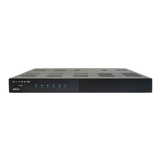
2.7 FRONT PANEL POWER MDX-12 POWER LED This LED turns blue when the amplifier is operating normally. It also indicates abnormal operation according to the codes below. In most cases, only the abnormal channel is shut down so the others can keep playing, and it resumes playing automatically once normal conditions are restored. -
Page 13: 2.8 Rear Panel
2.8 REAR PANEL 8 10 REAR VIEW 1:1 RCA inputs (1 per zone + 2 global inputs) RCA outputs (2 global outputs - looped) Source selection switches Speaker operating mode switches Volume Speaker Euroblock connectors Trigger input and output (looped) Operating mode switch (on/auto/trigger) AC inlet (IEC C18 type) 10. -
Page 14: Specifications
S P E C I F I C A T I O N S 3 years (parts and labor) Warranty Channels / Zones 12 channels / up to 6 zones Power Output RMS per Channel (8-Ohm) 75 Watts (2 channels driven) Power Output RMS per Channel (4-Ohm) 150 Watts (2 channels driven) High Output Mode (Bridged) RMS per Chan-... -
Page 15: Limited Warranty
Anthem shall have no obligation to correct any defect that is not reproducible by Anthem. If inspection by Anthem discloses that the repair required is not covered by this warranty, regular repair charges shall apply. - Page 16 DESIGNED IN NORTH AMERICA +1 905-564-1994 8:30 am - 5:00 pm M-F (ET) www.anthemAV.com 2024-02-07...
Need help?
Do you have a question about the MDX-12 and is the answer not in the manual?
Questions and answers