Table of Contents
Advertisement
Advertisement
Table of Contents

Related Manuals for Anthem Amp 1


Summary of Contents for Anthem Amp 1
- Page 1 A N T H E M A M P 1 O P E R A T I N G M A N U A L...
-
Page 2: Table Of Contents
C O N T E N T S page Parts List ...1 Front & Rear Panels ...2 Control Functions ...3 Connection Functions...3 Setting Up...4 Tube Insertion...5 Operation ...5 Troubleshooting ...6 Safety Instructions...7 Disclaimer of Liability...7 Warranty ...7 Bias Adjustments ...9 Technical Specifications...10 9/96 SKU# 56848... -
Page 3: What's In The Box
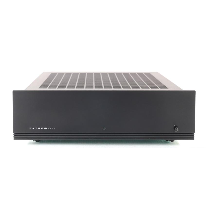
WHAT’S IN THE BOX? In addition to the Amp 1, it’s cover, and the operating manual you are presently reading (with associated inserts and warranty card), there are a few more items to take inventory of before steps are taken to make the Anthem Amp 1 operational. -
Page 5: Control Functions
4 ohm impedance. WARNING-DISCONNECT THE A C D E TA C H- A B L E P O W E RC O R D F R O M T H E AMP 1 AND WAIT 5 MINUTES BEFORE REMOV-... -
Page 6: Setting Up
12 AX7 (V2) FIRST S TAG E AMPL IF ICATION TUBE The first stage of amplification in the amplifier section of the Amp 1 is achieved through the use of this dual triode, amplifying both channels, one per triode section. The 12AX7 may be replaced with the ECC83 or 7025A tube. -
Page 7: Tube Insertion
F I G U R E 2 O P E R A T I O N Before plugging in the Amp 1, check to see that the unit is configured for the correct AC line voltage for country of use. The operating AC line voltage is indicated on the side of the shipping box. -
Page 8: Troubleshooting
T R O U B L E S H O O T I N G If at any time the Amp 1 fails to work properly, consult this checklist: 1. Check that the AC Detachable Power Cord is plugged into the Amp 1 Detachable Power Cord Socket (C) and is con- nected to a live source of AC power. -
Page 9: Safety Instructions
Do not stack any other component on top of the AMP 1 or block the ventilation slots in any way. Also, be sure that the AMP 1 is placed on a secure, hard and level surface, n o t on carpet. - Page 10 4. Sonic Frontiers, Inc. shall not be responsible in any way for consequential or indirect damages or liabilities resulting from the use and operation of the product covered herein or resulting from any breach of this warranty or any implied warranty relating to said product. During this period, Sonic Frontiers, Inc.
-
Page 11: Bias Adjustments
The Anthem AMP 1 has been designed to give many hours of listening pleasure and should only require biasing at tube replacement time.* Should one of the EL34 output tubes fail or otherwise require replacement, it will be necessary to adjust the out- put stage bias current. -
Page 12: Technical Specifications
T E C H N I C A L S P E C I F I C AT I O N S Specification ratings based on the nominal power line input for the country in which it is used 4 0 watts pe r channel continuous both channels driven, into 4 or 8 O hms (user selectable) , 20 Hz to 20 kHz w ith Typical power at cli pping (1% THD @ 1k Hz) 55 watts... - Page 13 D E S I G N E D A N D M A N U F A C T U R E D S O N I C F R O N T I E R S I N C O R P O R A T E D 2 7 9 0 B R I G H T O N R O A D , O A K V I L L E , O N T A R I O , C A N A D A L 6 H 5 T 4 T E L : ( 9 0 5 ) 8 2 9 - 3 8 3 8...
Need help?
Do you have a question about the Amp 1 and is the answer not in the manual?
Questions and answers