Autonics MP5Y Series Product Manual
Multi pulse meters
Hide thumbs
Also See for MP5Y Series:
- Manual (23 pages) ,
- Instruction manual (9 pages) ,
- Manual (23 pages)
Table of Contents
Advertisement
Quick Links
TCD230028AB
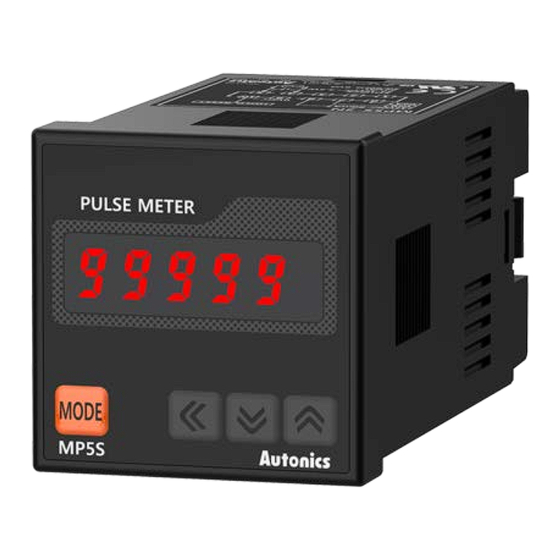
Multi Pulse Meters
MP5S / MP5Y / MP5W Series
PRODUCT MANUAL
For your safety, read and follow the considerations written in the instruction
manual, other manuals and Autonics website.
The specifications, dimensions, etc. are subject to change without notice for product
improvement. Some models may be discontinued without notice.
Features
• 16 operation modes
- Frequency / revolutions / speed, passing speed, cycle, passing time, time interval
- Time differential, absolute ratio, error ratio, density, error, length measurement 1 / 2,
interval
- Accumulation, addition / subtraction (individual input),
addition / subtraction (phase difference input)
• Various output models
- Relay triple / quintuple output, NPN / PNP open collector quintuple output
- BCD Dynamic output, PV transmission output (current output)
- RS485 communication output (Modbus RTU)
• Various function
- Prescale, delay monitoring, hysteresis, auto-zero, parameter lock, data bank (MP5W
only)
• Display range: -19999 to 99999
• Various display units
ᜢ ᜧ ᜫ
Safety Considerations
• Observe all 'Safety Considerations' for safe and proper operation to avoid hazards.
• symbol indicates caution due to special circumstances in which hazards may occur.
Warning
Failure to follow instructions may result in serious injury or death.
01. Fail-safe device must be installed when using the unit with machinery that
may cause serious injury or substantial economic loss. (e.g. nuclear power
control, medical equipment, ships, vehicles, railways, aircraft, combustion
apparatus, safety equipment, crime / disaster prevention devices, etc.)
Failure to follow this instruction may result in personal injury, economic loss or
fire.
02. Do not use the unit in the place where flammable / explosive / corrosive gas,
high humidity, direct sunlight, radiant heat, vibration, impact, or salinity
may be present.
Failure to follow this instruction may result in explosion or fire.
03. Install on a device panel to use.
Failure to follow this instruction may result in fire or electric shock.
04. Do not connect, repair, or inspect the unit while connected to a power
source.
Failure to follow this instruction may result in fire or electric shock.
05. Check 'Connections' before wiring.
Failure to follow this instruction may result in fire.
06. Do not disassemble or modify the unit.
Failure to follow this instruction may result in fire or electric shock.
Caution
Failure to follow instructions may result in injury or product damage.
01. When connecting the power / measurement input and relay output, use
AWG 24 (0.20 mm
) to AWG 15 (1.65 mm
2
screw with a tightening torque of 0.98 to 1.18 N m.
Use the wiring suitable for the load current capacity.
Failure to follow this instruction may result in fire or malfunction due to contact
failure.
02. Use the unit within the rated specifications.
Failure to follow this instruction may result in fire or product damage.
03. Use dry cloth to clean the unit, and do not use water or organic solvent.
Failure to follow this instruction may result in fire or electric shock.
04. Keep the product away from metal chip, dust, and wire residue which from
flowing into the unit.
Failure to follow this instruction may result in fire or product damage.
Cautions during Use
• Follow instructions in 'Cautions during Use' .
Otherwise, it may cause unexpected accidents.
• Power supply should be insulated and limited voltage / current or Class 2, SELV power
supply device.
• Install a power switch or circuit breaker in the easily accessible place for supplying or
disconnecting the power.
• Use twisted pair wire for communication line.
• Keep away from high voltage lines or power lines to prevent inductive noise.
In case installing power line and input signal line closely, use line filter or varistor
at power line and shielded wire at input signal line. Do not use near the equipment
which generates strong magnetic force or high frequency noise.
• This unit may be used in the following environments.
- Indoors (in the environment condition rated in 'Specifications')
- Altitude max. 2,000 m
- Pollution degree 2
- Installation category II
) cable and tighten the terminal
2
Advertisement
Table of Contents

Related Manuals for Autonics MP5Y Series


Summary of Contents for Autonics MP5Y Series
- Page 1 • Use twisted pair wire for communication line. • Keep away from high voltage lines or power lines to prevent inductive noise. manual, other manuals and Autonics website. In case installing power line and input signal line closely, use line filter or varistor The specifications, dimensions, etc.
-
Page 2: Ordering Information
2: 24 VACᜠ 50 / 60 Hz, 24 - 48 VDCᜡ Y: DIN W 72 × H 36 mm 4: 100 - 240 VACᜠ 50 / 60 Hz Download the installation file and the manuals from the Autonics website. W: DIN W 96 × H 48 mm ■ DAQMaster ❸... -
Page 3: Specifications
-|Transparent Guide|- Specifications ■ MP5W • Power / input terminal Series MP5S MP5Y MP5W Solid state input 1: ≤ 50 kHz (pulse width: ≥ 10 ㎲) Input signal Solid state input 2 : ≤ 5 kHz (spulse width: ≥ 100 ㎲) Contact input: ≤... -
Page 4: Mode Setting
-|Transparent Guide|- ■ Parameter 2 group Mode Setting Display Parameter Display Default Setting range condition → Parameter 0 group → [MODE] [MODE] [MP5W model] P2-1 Data bank 1, 2 pBANK → Parameter group → [MODE] 2 sec [MODE] 3 sec P1-1 Input Decimal operation... -
Page 5: Output Mode
-|Transparent Guide|- Output Mode Operation Mode ■ F1: frequency / revolutions / speed Output mode is available to set. (Indicator does not support output mode.) OFF: H: hysteresis Measures the frequency of input A and displays the calculated frequency, revolutions, and speed. - Page 6 -|Transparent Guide|- ■ F5: time interval ■ F9: density Displays measured time of input A ON. Measures and displays the density ratio (%) of input B against the total sum of input • t: measured time of input A ON [sec] A and input B.
- Page 7 -|Transparent Guide|- Functions ■ F13: accumulation Measures and displays the counted value of input A pulses. ■ Hysteresis • P: number of input A pulses Accumulation = P × α Near the comparative setting value, the output may turn ON / OFF frequently and •...
- Page 8 Segment Table The segments displayed on the product indicate the following meanings. It may differ depending on the product. 7 segment 11 segment 12 segment 16 segment 18, Bansong-ro 513Beon-gil, Haeundae-gu, Busan, Republic of Korea, 48002 www.autonics.com | +82-2-2048-1577 | sales@autonics.com...
Need help?
Do you have a question about the MP5Y Series and is the answer not in the manual?
Questions and answers