Table of Contents
Advertisement
Quick Links
TCD210074AB
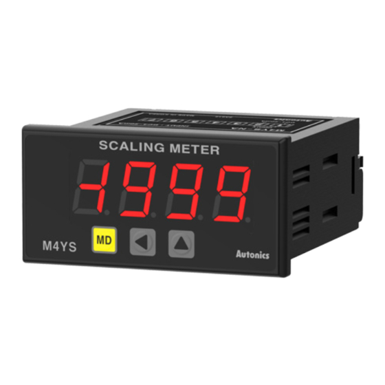
Loop-Power Panel Meters
(Indicator)
M4NS, M4YS Series
PRODUCT MANUAL
For your safety, read and follow the considerations written in the instruction
manual, other manuals and Autonics website.
The specifications, dimensions, etc. are subject to change without notice for product
improvement. Some models may be discontinued without notice.
Features
• Loop-powered: power supplied by loop current
• Measured input: DC 4 - 20 mA
• Display range: -1999 to 9999
• High / low-limit display scale function
• Decimal point setting function
• Input high / low-value correction function
• Display peak value monitoring function
• Set peak value monitoring delay time
• Display cycle time setting (0.5 / 1 / 2 / 3 / 4 / 5 seconds)
• Error display function
- M4NS: DIN W 48 × H 24 mm
- M4YS: DIN W 72 × H 36 mm
ᜫ
Safety Considerations
• Observe all 'Safety Considerations' for safe and proper operation to avoid hazards.
• symbol indicates caution due to special circumstances in which hazards may
occur.
Warning
Failure to follow instructions may result in serious injury or death.
01. Fail-safe device must be installed when using the unit with machinery that
may cause serious injury or substantial economic loss. (e.g. nuclear power
control, medical equipment, ships, vehicles, railways, aircraft, combustion
apparatus, safety equipment, crime / disaster prevention devices, etc.)
Failure to follow this instruction may result in personal injury, economic loss or fire.
02. Do not use the unit in the place where flammable / explosive / corrosive gas,
high humidity, direct sunlight, radiant heat, vibration, impact or salinity
may be present.
Failure to follow this instruction may result in explosion or fire.
03. Install on a device panel to use.
Failure to follow this instruction may result in fire.
04. Do not connect, repair, or inspect the unit while connected to a power
source.
Failure to follow this instruction may result in fire.
05. Check 'Connections' before wiring.
Failure to follow this instruction may result in fire.
06. Do not disassemble or modify the unit.
Failure to follow this instruction may result in fire.
Caution
Failure to follow instructions may result in injury or product damage.
01. When connecting the power / measurement input and relay output, use
AWG 24 (0.20 mm
) to AWG 15 (1.65 mm
2
terminal screw with a tightening torque of 0.98 to 1.18 N m.
Failure to follow this instruction may result in fire or malfunction due to contact
failure.
02. Use the unit within the rated specifications.
Failure to follow this instruction may result in fire or product damage.
03. Use a dry cloth to clean the unit, and do not use water or organic solvent.
Failure to follow this instruction may result in fire.
04. Keep the product away from metal chip, dust, and wire residue which flow
into the unit.
Failure to follow this instruction may result in fire or product damage.
Cautions during Use
• Follow instructions in 'Cautions during Use'.
Otherwise, It may cause unexpected accidents.
• Power supply should be insulated and limited voltage / current or Class 2, SELV power
supply device.
• Install a power switch or circuit breaker in the easily accessible place for supplying or
disconnecting the power.
• Keep away from high voltage lines or power lines to prevent inductive noise.
In case installing power line and input signal line closely, use line filter or varistor at
power line and shielded wire at input signal line.
Do not use near the equipment which generates strong magnetic force or high
frequency noise.
Connection with the line filter
Install the line filter
close to the panel meter
Panel meter
HI
110 / 220 VACᜠ
LOW
Earth ground
• This unit may be used in the following environments.
- Indoors (in the environment condition rated in 'Specifications')
- Altitude max. 2,000 m
- Pollution degree 2
- Installation category II
) cable or over and tighten the
2
Connection with the varistor
Panel meter
HI
110 / 220 VACᜠ
LOW
Advertisement
Table of Contents

Related Manuals for Autonics M4NS Series


Summary of Contents for Autonics M4NS Series
- Page 1 For your safety, read and follow the considerations written in the instruction close to the panel meter Panel meter Panel meter manual, other manuals and Autonics website. 110 / 220 VACᜠ 110 / 220 VACᜠ The specifications, dimensions, etc. are subject to change without notice for product improvement.
- Page 2 Specifications Dimensions Model M4NS-NA M4YS-NA DC 4 - 20 mA Input type • Unit: mm, For the detailed drawings, follow the Autonics website. Impedance between ≤ 600 Ω • M4NS-NA input lines 7-segment (red) LED 7-segment (red) LED Display method...
- Page 3 If the input current is 3 % lower than 4 mA, 16 mA × 3 % = 0.48 mA → 4 mA - 0.48 mA = 3.52 mA, so LLLL is displayed when the input current is below 3.52 mA. 18, Bansong-ro 513Beon-gil, Haeundae-gu, Busan, Republic of Korea, 48002 www.autonics.com | +82-2-2048-1577 | sales@autonics.com...
Need help?
Do you have a question about the M4NS Series and is the answer not in the manual?
Questions and answers