Table of Contents
Advertisement
Quick Links
TCD210231AB
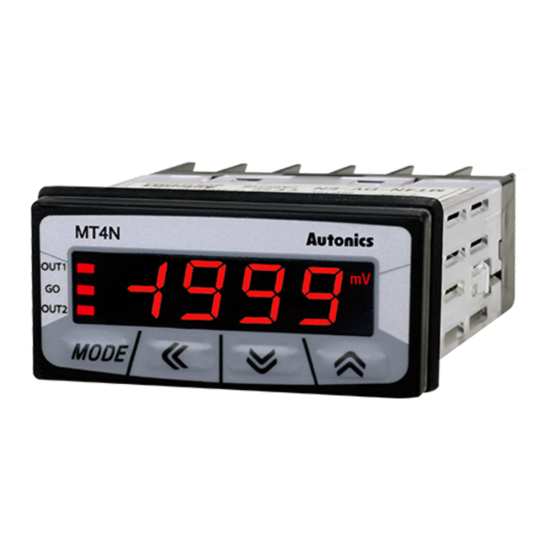
4-Digit Multi Panel Meters
MT4N Series
PRODUCT MANUAL
For your safety, read and follow the considerations written in the instruction
manual, other manuals and Autonics website.
The specifications, dimensions, etc. are subject to change without notice for product
improvement. Some models may be discontinued without notice.
Features
• Various input / output options (by model)
- Input options: DC voltage, DC current, AC voltage, AC current
- Output options: RS485 communication output, transmission output (DC 4 - 20 mA),
NPN / PNP open collector output,
relay contact output (default option: indicator / no output)
• Maximum allowed input: 50 VDCᜡ, DC 500 mA, 250 VACᜠ, AC 5A
• Display range: -1999 to 9999
• High / low-limit display scale function
• AC frequency measurement (range: 0.1 to 9999 Hz)
• Various functions: peak display value monitoring, display cycle delay, zero-point
adjustment, peak display value correction, PV transmission output
(DC 4 - 20 mA) scale, etc.
• Power supply: 12 - 24 VDCᜡ / VACᜠ, 100 - 240 VACᜠ
ᜢ ᜫ
Safety Considerations
• Observe all 'Safety Considerations' for safe and proper operation to avoid hazards.
• symbol indicates caution due to special circumstances in which hazards may occur.
Warning
Failure to follow instructions may result in serious injury or death.
01. Fail-safe device must be installed when using the unit with machinery that
may cause serious injury or substantial economic loss. (e.g. nuclear power
control, medical equipment, ships, vehicles, railways, aircraft, combustion
apparatus, safety equipment, crime / disaster prevention devices, etc.)
Failure to follow this instruction may result in personal injury, economic loss or fire.
02. Do not use the unit in the place where flammable / explosive / corrosive gas,
high humidity, direct sunlight, radiant heat, vibration, impact or salinity
may be present.
Failure to follow this instruction may result in explosion or fire.
03. Install on a device panel to use.
Failure to follow this instruction may result in fire or electric shock.
04. Do not connect, repair, or inspect the unit while connected to a power source.
Failure to follow this instruction may result in fire or electric shock.
05. Check 'Connections' before wiring.
Failure to follow this instruction may result in fire.
06. Do not disassemble or modify the unit.
Failure to follow this instruction may result in fire or electric shock.
Caution
Failure to follow instructions may result in injury or product damage.
01. When connecting the power / measurement input and relay output, use
AWG 24 (0.20 mm
) to AWG 16 (1.30 mm
2
terminal screw with a tightening torque of 0.78 to 0.98 N m.
Use the wiring suitable for the load current capacity.
Failure to follow this instruction may result in fire or malfunction due to contact
failure.
02. Use the unit within the rated specifications.
Failure to follow this instruction may result in fire or product damage.
03. Use a dry cloth to clean the unit, and do not use water or organic solvent.
Failure to follow this instruction may result in fire or electric shock.
04. Keep the product away from metal chip, dust, and wire residue which flow
into the unit.
Failure to follow this instruction may result in fire or product damage.
Cautions during Use
• Follow instructions in 'Cautions during Use' .
Otherwise, It may cause unexpected accidents.
• Power supply should be insulated and limited voltage / current or Class 2, SELV power
supply device.
• Install a power switch or circuit breaker in the easily accessible place for supplying or
disconnecting the power.
• Use twisted pair wire for communication line.
• Keep away from high voltage lines or power lines to prevent inductive noise.
In case installing power line and input signal line closely, use line filter or varistor at
power line and shielded wire at input signal line.
Do not use near the equipment which generates strong magnetic force or high
frequency noise.
Connection with the line filter
Install the line filter
close to the panel meter
Panel meter
HI
110 / 220 VACᜠ
LOW
Earth ground
• This unit may be used in the following environments.
- Indoors (in the environment condition rated in 'Specifications')
- Altitude max. 2,000 m
- Pollution degree 2
- Installation category II
)cable or over and tighten the
2
Connection with the varistor
Panel meter
HI
110 / 220 VACᜠ
LOW
Advertisement
Table of Contents

Related Manuals for Autonics MT4N Series


Summary of Contents for Autonics MT4N Series
- Page 1 For your safety, read and follow the considerations written in the instruction close to the panel meter Panel meter Panel meter manual, other manuals and Autonics website. 110 / 220 VACᜠ 110 / 220 VACᜠ The specifications, dimensions, etc. are subject to change without notice for product improvement.
- Page 2 Download the manuals from the Autonics website. ■ Output • 0: Relay • 1: NPN open collector Software Download the installation file and the manuals from the Autonics website. OUT1 OUT2 HOLD / ZERO HOLD / ZERO ■ DAQMaster...
- Page 3 -|Transparent Guide|- Specifications Mode Setting Model MT4N-DV-□□ MT4N-DA-□□ MT4N-AV-□□ MT4N-AA-□□ Parameter 1 → → [MODE] 3 sec [MODE] 3 sec group Input type DC voltage DC current AC voltage AC current Max. allowable input 110 % F.S. for each measured input range Parameter 2 →...
- Page 4 -|Transparent Guide|- ■ Parameter 2 group ■ Parameter 0 group Display Display Parameter Mark Defaults Setting range Parameter Mark Defaults Setting range condition condition [DC voltage model], [DC current model] OUT1 [OUT1 output model] -5 to 110 % of display range operation OFF, HI, LO, HL, HL-G 5)00...
- Page 5 -|Transparent Guide|- Output Operation Mode Function Description ■ Display method: frequency • The below describes based on OUT1. • OUT1 and OUT2 of output operations are same. It operates individually by the set output It measures input signal frequency when it is AC input. In order to measure frequency normally, input signal, over 10 % F.S.
- Page 6 Segment Table The segments displayed on the product indicate the following meanings. It may differ depending on the product. 7 segment 11 segment 12 segment 16 segment 18, Bansong-ro 513Beon-gil, Haeundae-gu, Busan, Republic of Korea, 48002 www.autonics.com | +82-2-2048-1577 | sales@autonics.com...
Need help?
Do you have a question about the MT4N Series and is the answer not in the manual?
Questions and answers