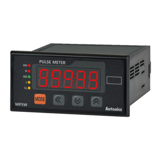
Summary of Contents for Autonics MP-XGT
- Page 1 MP-XGT(RS485) Technical Support Manual © Copyright Reserved Autonics Co., Ltd.
- Page 2 © Copyright Reserved Autonics Co., Ltd.
-
Page 3: Preface
Preface Preface Thank you very much for selecting Autonics products. Please familiarize yourself with the information contained in the Safety Precautions section before using this product. This user manual contains information about the product and its proper use, and should be kept in a place where it will be easy to access. -
Page 4: Technical Support Manual Guide
(www.autonics.com) to download a copy. The manual's content may vary depending on changes to the product's software and other unforeseen developments within Autonics, and is subject to change without prior notice. Upgrade notice is provided through our homepage. ... -
Page 5: Technical Support Manual Symbols
Failure to follow instructions can result in serious injury or death. Failure to follow instructions can lead to a minor injury or product damage. An example of the concerned feature's use. Annotation mark. ※1 © Copyright Reserved Autonics Co., Ltd. -
Page 6: Safety Precautions
Failure to follow these instructions may result in electric shock or fire. Do not use the unit where flammable or explosive gas, humidity, direct sunlight, radiant heat, vibration, and impact may be present. Failure to follow this instruction may result in fire or explosion. © Copyright Reserved Autonics Co., Ltd. - Page 7 Keep dust and wire residue from flowing into the unit. Failure may result in fire or product malfunction. Check the polarity of the measurement input contact before wiring the unit. Failure to follow this instruction may result in fire or explosion. © Copyright Reserved Autonics Co., Ltd.
- Page 8 Safety Precautions © Copyright Reserved Autonics Co., Ltd.
-
Page 9: Table Of Contents
Table of Contents ......................9 System ....................... 11 Version ........................ 11 Connections ......................11 Communication cable connection ............... 11 Communication Setting ................13 MP5W Setting ..................... 13 XG5000 Setting ....................14 Operation Check ..................23 © Copyright Reserved Autonics Co., Ltd. - Page 10 Table of Contents © Copyright Reserved Autonics Co., Ltd.
-
Page 11: System
RS-485 RS-485 RS-485 RS-485 XGK-CPUE MP5W MP5W MP5W MP5W (XGl-CH2A) Communication cable connection MP5W Cable connection PLC (XGT-XGL-CH2A) RX - RS – 485 (-) RX + TX - RS – 485 (+) TX + © Copyright Reserved Autonics Co., Ltd. - Page 12 1 System © Copyright Reserved Autonics Co., Ltd.
-
Page 13: Communication Setting
* If there is no additional key operation within 60 sec after entering into setting mode, it will be automatically returned to RUN mode and previous set value will be remained. * Check that RS485 communication models are only available communication. © Copyright Reserved Autonics Co., Ltd. -
Page 14: Xg5000 Setting
2 Communication Setting XG5000 Setting 1st Run XG5000, and select [Project] – [New Project] on menu. Enter project name and select CPU Series and type. © Copyright Reserved Autonics Co., Ltd. - Page 15 2 Communication Setting 2nd After executing, enter the below contents at XG5000. * This communication program is only for test. Before using it at field, review and test the program fully. © Copyright Reserved Autonics Co., Ltd.
- Page 16 USB. After completing connection, select [Online] – [Mode Switch] – [Stop]. Connection settings Settings Type Depth Local 4th At [Online] – [Diagnose] – [I/O Information] , click ‘I/O Sync’. After I/O synchronize, the settings are set as using module settings. © Copyright Reserved Autonics Co., Ltd.
- Page 17 6th [Standard Settings-Cnet] dialog box appears. At standard settings, set as below. Item Setting Note Communication type RS-485 Fixed Communication Standard 38400 User setting speed Settings Channel 2 Terminating resisters Disable User setting Station No. User setting Operation Channel 2 Use P2P mode © Copyright Reserved Autonics Co., Ltd.
- Page 18 7th At advanced settings, set as below. Item Channel 2 Data bit Advanced Stop bit settings Parity bit NONE 8th At Project window, select the communication module and [Add Item] – [P2P Communication] and click ‘OK’. © Copyright Reserved Autonics Co., Ltd.
- Page 19 2 Communication Setting 9th Double-click ‘P2P Channel’ and select ‘Modbus RTU client’ of ‘Use P2P’. Click ‘OK’. © Copyright Reserved Autonics Co., Ltd.
- Page 20 Click ‘Setting’ to set variable. * Modbus Mapping Table Type Setting range Factory default Address 301002(03E9) Present -19999 to 99999 value 301003(03EA) * Be sure that MP Series requires 2 addresses; 03E9, 03EA for reading present value. © Copyright Reserved Autonics Co., Ltd.
- Page 21 Read area Save area Address (setting) (setting) (fixed) Station 1 0x303E9 D00000 N00021 Station 2 0x303E9 D00002 N00062 Station 3 0x303E9 D00004 N00103 Station 4 0x303E9 D00006 N00144 Address Type Note 301002(03E9) Present value 301003(03EA) © Copyright Reserved Autonics Co., Ltd.
- Page 22 2 Communication Setting 11th At [Online] – [Connection Settings], select connection type. Select [Online] – [Write] to execute download. © Copyright Reserved Autonics Co., Ltd.
-
Page 23: Operation Check
3 Operation Check Operation Check © Copyright Reserved Autonics Co., Ltd. - Page 24 3 Operation Check © Copyright Reserved Autonics Co., Ltd.


Need help?
Do you have a question about the MP-XGT and is the answer not in the manual?
Questions and answers