Advertisement
Quick Links
RCL03 | RCL04
EN
Models
LED
P1
1
2
3
X5
X6
T2
14 11 12
24
21
22
CH1
CH2
T1
RCL03E5002B01
Degree of protection IP20
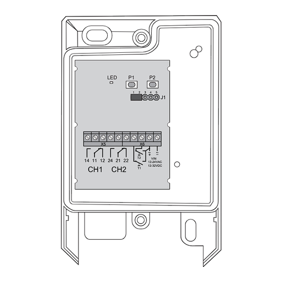
LED
P1
P2
1
2
3
4
5
J1
X5
X6
~
~
+
T2
VIN
14 11 12
24
21
22
12-24VAC
CH1
CH2
12-32VDC
T1
RCL04E5002B01
Degree of protection IP65
Technical Details
Frequency:
868.30 MHz
Modulation:
FSK
Coding:
Easywave
Power supply:
- AC:
12-24 V
- DC:
12-32 V
Current consumption:
0.18 W standby
0.6 W relay switched
(w/o load)
Degree of protection:
RCL03: IP20
RCL04: IP65
Input:
2 external buttons
Output:
2 potential-free
relay contacts
(changeover)
Max. contact rating:
- AC:
60 V / 1 A / 60 VA
- DC:
60 V / 1 A / 30 W
Operating temperature: -20°C to +60°C
Dimensions:
RCL03: 70 / 64 / 35 mm
RCL04: 72 / 114 / 36 mm
Weight:
RCL03: approx. 50 g
RCL04: approx. 100 g
Scope of Delivery
Mini receiver, mounting accessories (RCL03:
adhesive pad, RCL04: screws and anchors),
operating instructions
Intended Use
The unit may only be operated with safety extra
low voltage (SELV) and may only be used as a ra-
dio control for switching devices with safety extra
low voltage (SELV).
The manufacturer shall not be liable for any dam-
age caused by improper or non-intended use!
Mini Receiver
Safety Advice
P2
Caution! Observe the permissible supply volt-
4
5
J1
age and the max. contact rating!
Have faulty radio controls checked by the
manufacturer!
Do not make any unauthorized alterations or
modifications to the receiver!
~
~
+
VIN
12-24VAC
12-32VDC
Function
The RCL03 and RCL04 Easywave mini receivers
can be operated in a voltage range of 12-24 V AC
or 12-32 V DC.
Two potential-free relay outputs may be switched.
A total of 32 different Easywave radio transmis-
sion codes can be programmed. The memory
slots can be divided between the two outputs as
required.
If a transmitter is programmed into both outputs, it
still only occupies one memory slot.
It is also possible to connect one external but-
ton for each channel which can then be used to
switch the corresponding relay according to the
selected operating mode.
To do this, the button inputs T1 and T2 must be
wired to the supply voltage VIN1.
Operating Modes
The radio control can be operated in five differ-
ent operating modes with Easywave transmitters
for 1-button-, 2-button- or 3-button operation. The
operating mode can be selected with jumper J1.
PULSE
(1-button operation)
If a transmitter button or an external button is
pressed, the corresponding relay is triggered for
1 second.
ON/OFF
(2-button operation)
Each relay can be switched separately ON and
OFF.
The external buttons toggle between ON and
OFF in this operation mode.
transmitter button
A or C
B or D
MOTOR CONTROL
(UP/DOWN)
(2-button operation)
The relays are controlled in combination and
are interlocked.
STOP with opposite direction
transmitter button
A or C
External button T1
B or D
External button T2
The maximum runtime is 90 seconds.
Carefully read through these instruc-
tions before connecting and operating
the receiver!
1
J1
1
J1
function
ON
OFF
1
J1
function
UP
STOP
for DOWN direction
DOWN
STOP
for UP direction
DEAD MAN´S MODE
(1-button operation)
Each relay can be switched separately. The relay
is triggered as long as the corresponding trans-
mitter button or the corresponding external but-
ton is pressed (transmitter button operation max.
36 secs).
MOTOR CONTROL
(UP/STOP/DOWN)
(3-button resp. 4-button operation)
The relays are controlled in combination and are
interlocked.
transmitter button
A
B
C
D
The external buttons behave as if they are
in 2-button motor operation mode!
The maximum runtime is 90 seconds.
Mounting and Connecting
1. Remove the housing cover.
2. Mount the receiver on a suitable location, us-
ing the mounting accessories supplied.
Make sure there is no interference with
the wireless connection. Do not mount
the device in a distribution box, in metal
casings, in direct proximity to large met-
al objects, on the floor or close to it.
The maximum length of all connecting
cables may not exceed 3 m!
When connecting the RCL04, insert
2
3 4
5
all connection cables into the device
through the opening on the bottom via
the watertight PG screw connections.
3. Select the desired operating mode with the
jumper J1.
4. Connect the supply voltage and the safety
2
3 4
5
extra-low voltage devices according to the
connection diagram.
or
Connect the supply voltage and the devices
to be switched for the motor control according
to the connection diagram.
In the MOTOR operating mode, the
receiver may only be operated with
12-32 V DC.
5. If necessary, connect the external buttons to
the terminal T1 and T2.
The external buttons always use the
2
3 4
5
operation mode, currently set with the
jumper J1.
6. Program the codes of the transmitters to the
receiver (see section "Program transmitters").
7. Put the housing cover back on.
1
2
3 4
5
J1
1
2
3 4
5
J1
function
UP
DOWN
STOP
STOP
Advertisement

Related Manuals for Eldat Easywave RCL03


Summary of Contents for Eldat Easywave RCL03
- Page 1 RCL03 | RCL04 Mini Receiver Models Safety Advice DEAD MAN´S MODE (1-button operation) Carefully read through these instruc- Each relay can be switched separately. The relay tions before connecting and operating is triggered as long as the corresponding trans- the receiver! Caution! Observe the permissible supply volt- mitter button or the corresponding external but- ton is pressed (transmitter button operation max.
- Page 2 - normally open contact: terminals 11 + 14 Leave the programming mode, by briefly pres- Hereby, ELDAT EaS GmbH declares that the radio - normally closed contact: terminals 11 + 12 sing P1 or P2 again. The LED turns off.
Need help?
Do you have a question about the Easywave RCL03 and is the answer not in the manual?
Questions and answers