Table of Contents
Advertisement
Quick Links
Advertisement
Table of Contents

Related Manuals for Sawo INP-C-V2


Summary of Contents for Sawo INP-C-V2
- Page 1 MANUAL POWER CONTROLLER 2.0 Not for use in the USA, Canada and Mexico. ENGLISH...
-
Page 2: Table Of Contents
TABLE OF CONTENTS Introduction of the Innova Control ..............3 Precautions .......................3 Power Controller ....................4 Control Unit to Heater ..................5 Contactor Unit ....................6 Sensors ......................6 Sensor location with heaters mounted on the wall ....... 7 Sensor location with heaters mounted on the floor ......7 Technical Diagram .....................8 Maximum Session Time ...................10 Door Sensor ....................10... -
Page 3: Introduction Of The Innova Control
INTRODUCTION OF THE INNOVA CONTROL Congratulations on your purchase of Innova Control Unit! Innova Control Unit is developed to enhance your sauna bathing with a variety of different features. It can adjust temperature, humidity, ventilation and light option in your sauna. The Innova Control Units are available on a separate or built-in mounting on the Power Controller. -
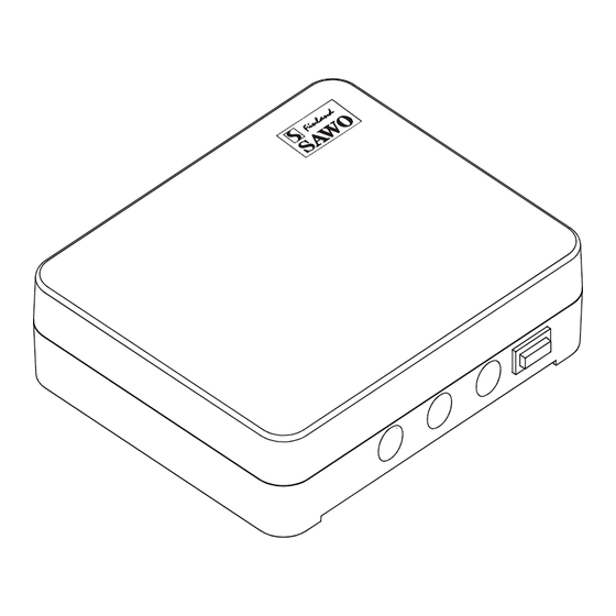
Page 4: Power Controller
Power Controller The heater is connected to the electrical The Power controller or the separate control network semi-stationarily with a H07RN-F panel must not be located inside the sauna rubber cable or its equivalent. The use of room or in places where temperature PVC-insulated cable as a connecting cable can exceed 40°C. -
Page 5: Control Unit To Heater
Control Unit to Heater Connection Diagram Fig. 3 INSIDE THE SAUNA ROOM OUTSIDE THE SAUNA ROOM SEPARATE CONROL PANEL SENSOR(S) POWER CONTROLLER HEATER *) Bench sensor Junction Box is optional max. 500mm Floor INSIDE THE SAUNA ROOM OUTSIDE THE SAUNA ROOM SENSOR(S) POWER CONTROLLER WITH BUILT-IN CONTROL PANEL... -
Page 6: Contactor Unit
Contactor Unit Follow the instructions that are supplied If the heater used is more than 15 kW, together with the contactor unit. an additional contactor is needed. The contactor unit is linked to the main Power Controller with a RJ12 cable (Fig.4). Installation of separate control panel with Installation of power controller with built- Fig. -
Page 7: Sensor Location With Heaters Mounted On The Wall
Sensor location with heaters mounted on the wall Fig. 5 TEMPERATURE SENSOR WITH FUSE ON THE WALL Air Vent Sensor 2 (Optional) Temperature Sensor See Airvent installation NOTE Do not place the sensors too near to air ventilation (not under 1000mm) or not under 500mm from air ventilation, which is directed away from sensors. -
Page 8: Technical Diagram
Technical Diagram For Built-in Controls, Control Unit Main Switch Built-in Control Jumper For 1 1 0 1 Models remove the interface Maximum Session Time Fig. 9 PCB to access the (hours) Session Time jumper. Adjust this jumper Make sure that pin header to change max. -
Page 9: Maximum Session Time
Maximum Session Time The maximum heater on-time is set by the jumpers on SCB1 in the power controller, The maximum sauna session time depends Figure 11. Jumpers 3, 4 and 5 are meant on the purpose of the sauna. For domestic only for public sauna rooms. -
Page 10: The Control Unit Main Switch
The Control Unit Main Switch The control unit switch can be found on the top end of the unit. Using this switch, you can isolate the electronics from the mains power supply. UNIT ON LIGHT ON ENGLISH... - Page 11 Description Power Rating Remarks Description Power Rating Remarks Control Steamer Rated Power 3 Phases 5kW AC1 Rated Power 3 Phases 15kW AC1 Rated Power Single Phase 3kW AC1 (3 x 5kW) Rated Voltage 230V 1N~ Rated Voltage 3 Phases 400V 3N~ Switching capacity 21A (3 Phases), Rated Power Single Phase...
- Page 12 PX 4 Subject to change without notice. www.sawo.com | info@sawo.com...
Need help?
Do you have a question about the INP-C-V2 and is the answer not in the manual?
Questions and answers