Table of Contents
Advertisement
Quick Links
Advertisement
Table of Contents

Related Manuals for Sawo Innova Classic 2.0


Summary of Contents for Sawo Innova Classic 2.0
- Page 1 CONTROLS INSTRUCTIONS MANUAL ENGLISH...
-
Page 2: Table Of Contents
Table of Contents 1. Introduction of the Innova Controls 1.1 Precautions 2. Operating Instructions 2.1 Quick Start 2.2 Direction of Use 2.2.1 Heater on 2.2.2 Heater off 2.2.3 Pre-run Button 2.2.4 Setting Mode 2.2.5 Dimmer Light (Optional) 2.2.6 Fan (Optional) 2.2.7 Cabin Light Button 2.2.8 Key Pad Lock 2.3 Steamer Functions... -
Page 3: Introduction Of The Innova Controls
1. Introduction of the Innova Controls Congratulations on your purchase of Innova Control Unit! Innova Control Unit is developed to enhance your sauna bathing with a variety of different features. It can adjust temperature, humidity, ventilation and light option in your sauna. The Innova Control Units are available on a separate or built-in mounting on the Power Controller. -
Page 4: Operating Instructions
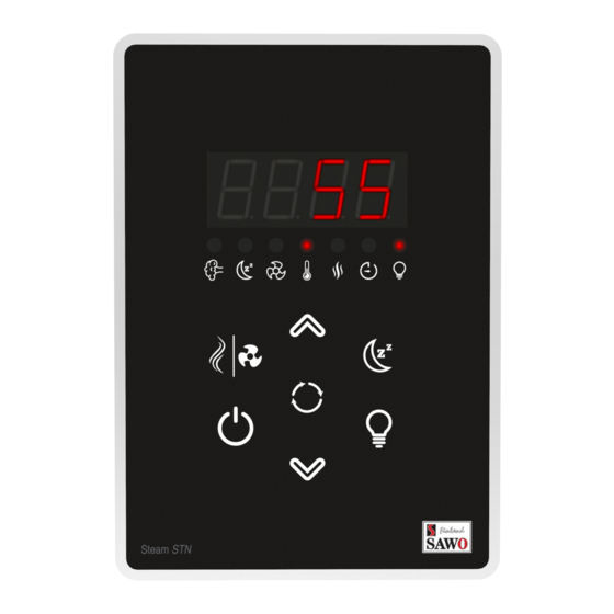
* For illustration purposes only. Buttons and States (Illustration) LED display LED indicators Light Heater Timer Steamer Relative Humidity (Optional) (Optional) Mode Pre-run Timer Temperature Toggle / (Optional) Select Power Light Down 2. Operating Instructions 2.1 Quick Start Switch the power “ON” by pressing the Power button. First the software versions will be displayed. -
Page 5: Direction Of Use
2.2 Directions of use 2.2.1 Heater on Press the Power button to activate the When the control unit is in the pre-run state, it will display the remaining time of the heater. The heater LED is illuminated pre-run. The confirmed pre-run settings are indicating that the heater is turned on. -
Page 6: Setting Mode
2.2.4 Setting Mode 2.2.8 Key pad lock Long press the toggle button to activate (to prevent unauthorised use of setting mode. It can be used to select and control unit) adjust the fan*, temperature, humidity* and Lock the key pad by pressing the up and the session time (*not all models have all down arrow keys at the same time for more the same features). -
Page 7: Water Refill
2.3.3 Cabin drying The state for “HOT” depends on the second 10 minutes after the steamer session, the sensor, the bench sensor. If it is a heater will automatically dry the sauna temperature sensor only, and the bench room. The cabin drying is set to 30 minutes temperature in the sauna room is 56°C or more, the steamer cannot be activated. -
Page 8: Assembly And Installation
3. Assembly and Installation The Innova Control Unit consists of the Innova Control Panel (Separate or Built-in), Power Controller and Sensor. The Control Panel and Power Controller communicate by using RJ12 cable. 3.1 Control Unit to Heater Connection Diagram Fig.1 INSIDE THE SAUNA ROOM OUTSIDE THE SAUNA ROOM SEPARATE CONROL PANEL... -
Page 9: Technical Diagram
For Built-in Controls, Control Unit Main Switch Built-in Control Jumper For 3.2 Technical Diagram 1 1 0 1 Models remove the interface Maximum Session Time PCB to access the (hours) Fig. 2 Session Time jumper. Adjust this jumper Make sure that pin header to change max. -
Page 10: Power Controller
3.3 Power Controller The Power controller or the separate The heater is connected to the electrical control panel must not be located inside the network semi-stationarily with a H07RN-F sauna room or in places where temperature rubber cable or its equivalent. The use of can exceed 40°C. -
Page 11: Sensors
3.5 Sensors on the wall above the heater. Place the sensor 150mm from the ceiling (Fig. 6 & 7). One or two sensors can be connected to the Power Controller. The first sensor measures However, if the heater is more than 200mm the temperature, it is the sensor with from the wall, place the sensor to the temperature fuse and thermistor. -
Page 12: Maximum Session Time
3.5.2 Sensor location with heaters mounted on the floor more than 200mm from the wall Top view Side view See Airvent Installation AIR VENT Fig.8 Fig.9 AIR VENT Temperature Sensor SENSOR 2 (Optional) CEILING Sensor SENSOR LOCATION AIR VENT Sensor See Airvent installation WALL... -
Page 13: Door Sensor (Optional)
3.7 Door Sensor 3.8 Fan In other than household use, it is recom- The fan function can only be activated if the mended to install door sensor. The door fan feature is present on the control unit. sensor disables all pre-run operations if the Ensure that the fan motor to be controlled is door is opened while the pre-run count- either shaded pole or permanent split... -
Page 14: Installation For Separate Control Panel
3.11 Installation for Separate Control Panel (See IIlustration) Mount the Separate control panel Insert the casing on the cut section. Screw the Control panel to the wall casing outside the sauna room, in preferred, secure area on a room on the holes provided. Snap the top cover of the panel to its temperature. -
Page 15: Troubleshooting
4. Troubleshooting If an error occurs, the heater will be Warning switched off. There will be a warning beep and the code for the error will be Please note, only a qualified electrician or displayed in the control panel. maintenance personnel is allowed to make the service operations and repairs! See more details on the table below. - Page 16 Other possible problems are: The control unit is working fine, but the The user switches the steamer on and heater does not turn on. Check the “dry” is displayed immediately. Check electricity supply to the heater. Check that the “empty” and “tank level” that the wires for the sensors are terminals from the heater are placed into the correct terminals in the...
- Page 17 LED lights, compact fluorescent lights and other similar lights are not compatible with Innova sauna controller. Damages caused by connecting these non-compatible lights are not covered by warranty. www.sawo.com Subject to change without notice. info@sawo.com...
Need help?
Do you have a question about the Innova Classic 2.0 and is the answer not in the manual?
Questions and answers