Nibe FLM Installer Manual
Exhaust air module
Hide thumbs
Also See for FLM:
- Installer manual (40 pages) ,
- User manual (24 pages) ,
- Installer manual (36 pages)
Table of Contents
Advertisement
Quick Links
Advertisement
Table of Contents

Related Manuals for Nibe FLM


Summary of Contents for Nibe FLM
- Page 1 IHB EN 2115-1 INSTALLER MANUAL 631225 Exhaust air module NIBE FLM...
-
Page 3: Table Of Contents
2 Delivery and handling 8 Service Transport Assembly Service actions Supplied components 9 Disturbances in comfort Compatible NIBE heat pumps Troubleshooting Removing the covers Mounting 10 Accessories 3 The design of the exhaust air module 11 Technical data Pipe connections... -
Page 4: Important Information Safety Information
©NIBE 2021. Caution You need the product's (14 digit) serial number If the supply cable is damaged, only NIBE, for servicing and support. its service representative or similar author- ised person may replace it to prevent any RECOVERY danger and damage. - Page 5 System flushed System vented Antifreeze Expansion vessel Particle filter Safety valve Shut off valves Circulation pump setting Checking the condensation water seal Trim valve Electricity Connections Phase voltage Supply connected 230 V Circuit fuses NIBE FLM Chapter 1 | Important information...
-
Page 6: Delivery And Handling
10 mm is left to reduce the risk of noise and Assembly of any vibrations being propagated. NIBE FLM is installed on top of the ground source heat pump or independently on brackets. Noise from the circulation pump or fan can be transferred to the brack- ets. -
Page 7: Supplied Components
2 x screws (T25) for in- Ø 20 mm stalling NIBE FLM on NIBE heat pump LOCATION The bag of supplied items is placed on top of NIBE FLM. Compatible NIBE heat SIDE COVERS Undo the screws at the upper edge. pumps Lift the side hatches upwards and twist the cover outwards slightly. -
Page 8: Mounting
Remove the front cover from the heat pump. Remove the top panel from the heat pump (installed with 6 screws). Install NIBE FLM from the top and slide into position. Secure NIBE FLM with the 2 screws supplied. Chapter 2 | Delivery and handling... -
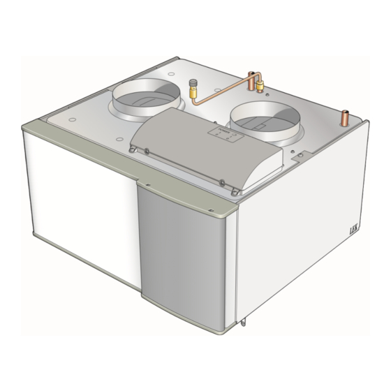
Page 9: The Design Of The Exhaust Air Module
3 The design of the exhaust air module BT21 XL32 QM21 XL31 BT20 HQ10 AA100 BT20 XL31 QM21 XL32 BT26 BT27 HQ10 AA100 BT21 EP16 XL40 BT27 BT26 NIBE FLM Chapter 3 | The design of the exhaust air module... -
Page 10: Pipe Connections
BT20 Temperature sensor, exhaust air Type plate BT21 Temperature sensor, extract air Designations according to standard EN 81346-2. BT26 Temperature sensor, collector in BT27 Temperature sensor, collector out Chapter 3 | The design of the exhaust air module NIBE FLM... -
Page 11: Pipe And Ventilation Connections
Venting takes place Pressure gauge through vent valve (QM21). When venting, set the switch for the circulation pump (SF2) to Safety valve position "0". Trim valve Manual reversing valve/shunt Bore hole Ground collector NIBE FLM Chapter 4 | Pipe and ventilation connections... -
Page 12: Dimensions And Pipe Connections
-10°C to +20 °C for the brine at a pre-pressure of 0.5 bar and with the safety valve’s opening pressure set at 3 bar. Expansion vessel Storlek Size 1000 Köldbärarvolym Brine volume Chapter 4 | Pipe and ventilation connections NIBE FLM... -
Page 13: Condensation Water Hose
Condensation water Installation alternative hose ANOTHER HEAT PUMP When NIBE FLM is installed together with another heat Connect the condensation water hose to the drip- pump, the brine circuit is supplied with a trim valve pan drain (XL40). (RN1). This is necessary for adjusting the brine flow. - Page 14 The external fan (GQ4) takes over ventilation, which is led out of the house without recovery. At the same time, NIBE FLM circulates air to and from other rooms where cooling is required, normally two to three bedrooms. QM40 QM41...
-
Page 15: General Ventilation Connection
Always use a kitchen fan when cooking. Ventilation flow Connect NIBE FLM so that all the exhaust air, except kitchen duct air (kitchen fan), passes through the heat exchanger (EP16) in the product. The ventilation flow must comply with the applicable national standards. -
Page 16: Electrical Connections
CONNECTING TO COMPATIBLE HEAT PUMP General Connection of supply to NIBE FLM no. 1 There is the option to connect the supply for NIBE FLM NOTE no. 1 on the terminal block in the heat pump. With this All electrical connections must be carried out type of connection, the plug on the supply cable (W1) by an authorised electrician. - Page 17 F1245/F1255 Connecting the supply to NIBE FLM no. 2-4 F1345/F1355 NIBE FLM no. 2-4 connects to an earthed single phase wall socket or a permanent installation. For permanent installations, NIBE FLM has to be preceded by a circuit breaker with at least a 3 mm breaking gap.
- Page 18 F1345 and on terminal block AA101:X10 in F1345 2.0/F1355. NIBE FLM no. 3 connects to the accessory board’s ter- minal block (AA5-X4) in NIBE FLM no. 2. AA5-S2 NIBE FLM no. 4 connects in a similar way in NIBE FLM AA5-S2 no. 3. Compatible heat pump AA101:X10...
- Page 19 For permanent install- temperature is wanted. ations, NIBE FLM must be preceded by a circuit breaker A suitable location is on a free inner wall in a hall approx. with at least a 3 mm breaking gap.
- Page 20 F1245/F1255 Connection of duct fan and damper for FLM cooling Room sensor (AZ10-BT50) is connected to any AUX input (AA3-X6:9-18). Connect the fan (GQ4) and the damper (QM40) (QM41) for AA5-X9:4 (signal), AA5-X9:3 (N) and AA5-X10:2 (230V). External F1245/F1255 The connection on AA5-X10 and PE are occupied and these must be spliced with a clamp.
-
Page 21: Commissioning And Adjusting Preparations
Check that the filling valves are fully closed. Filling and venting Caution -QZ20 Insufficient venting can damage internal com- ponents in NIBE FLM. FILLING AND VENTING THE BRINE SYSTEM NOTE When filling the brine system, mix the water with anti- Venting may be necessary during installation freeze in an open container. -
Page 22: Start-Up And Inspection
STARTING-UP WITH ANOTHER HEAT PUMP Start-up and Set the main switch (SF1) and the switch for the inspection circulation pump (SF2) on NIBE FLM to position “1”. Check that the fan (GQ2) and the circulation pump (GP2) are in operation. NOTE... - Page 23 STARTING-UP WITH VENTILATION ONLY SETTING THE BRINE FLOW It is possible to run NIBE FLM with only ventilation, e.g. Set the brine flow so that the temperature difference before the brine side is ready for connection. In this between the brine entering and leaving NIBE FLM is mode, the circulation pump must be switched off.
- Page 24 Capacity circulation pump Pressure Tryck (kPa) 100% 1000 1200 Flow Flöde (l/h) Output circulation pump Effekt Output 100% 1000 1200 Flow Flöde (l/h) Chapter 6 | Commissioning and adjusting NIBE FLM...
-
Page 25: Program Settings
7 Program settings The activation of NIBE FLM can be performed via the start temp. exhaust air start guide or directly in the menu system in the com- Here you set the indoor temperature at which night patible heat pump. - Page 26 Set the start and stop values here. Cooling is activated at the set start value + difference and cools to the stop value. FLM cooling always runs at fan speed 3. Caution Cooling can be activated at the same time as there is a heating demand.
-
Page 27: Service
It is usually easier to start the circulation pump with NIBE FLM running, and with the switch (SF1) set to "1". If the circulation pump is helped to start while NIBE FLM is running, be prepared for the screwdriver to jerk when the pump starts. -
Page 28: Disturbances In Comfort
• Fan speed in forced mode. function (a malfunction can lead to disturbance in com- – If NIBE FLM is connected to a compatible heat fort) and indicates this with alarms and action instruc- pump: Enter menu 1.2 and select "normal". -
Page 29: Accessories
Detailed information about the accessories and complete accessories list available at nibe.eu. Not all accessories are available on all markets. BRACKET BAU 40 Wall mounting of NIBE FLM. Part no. 067 666 TOP CABINET TOC 30 Top cabinet, which conceals any pipes/ventilation ducts. -
Page 30: Technical Data
11 Technical data Dimensions and setting-out coordinates Ø160 Chapter 11 | Technical data NIBE FLM... -
Page 31: Technical Specifications
Technical specifications NIBE FLM Electrical data Supply voltage 230 V NAC 50 Hz Max driving power circulation pump Driving power fan Enclosure class IP21 Ventilation Max airflow Brine circuit Minimum incoming brine temperature °C Maximum recommended incoming brine temperature °C Maximum outgoing brine temperature °C... -
Page 32: Electrical Circuit Diagram
Electrical circuit diagram Chapter 11 | Technical data NIBE FLM... - Page 33 NIBE FLM Chapter 11 | Technical data...
-
Page 34: Item Register
Marking, 4 Preparations, 21 Mounting, 8 Start-up and inspection, 22 Connecting to another heat pump, 8 Compatible NIBE heat pumps, 7 Connecting to F1145/F1155/F1245/F1255, 8 Condensation water hose, 13 Connecting to another heat pump, 19 Outline diagram, 11 Connecting to compatible heat pump, 16... - Page 35 Symbol key, 11 Symbols, 4 Technical data, 30 Dimensions and setting-out coordinates, 30 Technical Data, 31 Technical Data, 31 The design of the exhaust air module, 9 List of components, 10 Transport Assembly, 6 Troubleshooting, 28 NIBE FLM Item register...
-
Page 39: Contact Information
Tel: +46 (0)433-27 3000 info@evan.ru info@nibe.se nibe-evan.ru nibe.se SWITZERLAND NIBE Wärmetechnik c/o ait Schweiz Industriepark, CH-6246 Altishofen Tel. +41 (0)58 252 21 00 info@nibe.ch nibe.ch For countries not mentioned in this list, contact NIBE Sweden or check nibe.eu for more information. - Page 40 WS release date: 2021-03-23 07:27 Publish date: 2021-04-14 13:26 This manual is a publication from NIBE Energy Systems. All product illustrations, facts and data are based on the available information at the time of the publication’s approval. NIBE Energy Systems makes reservations for any factual or printing errors in this manual.
Need help?
Do you have a question about the FLM and is the answer not in the manual?
Questions and answers