Burster RESISTOMAT 2311 Operation Manual
Hide thumbs
Also See for RESISTOMAT 2311:
- Operation manual (17 pages) ,
- Operation manual (20 pages) ,
- Manual (41 pages)
Table of Contents
Advertisement
Quick Links
© 2024
burster
präzisionsmesstechnik gmbh & co. kg
All rights reserved
Valid
March 8, 2024
from:
OPERATION MANUAL
RESISTOMAT
Model 2311
®
Manufacturer:
burster
präzisionsmesstechnik gmbh & co. kg
Talstrasse 1 - 5
76593 Gernsbach
Germany
Tel.: +49 7224 645-0
Fax: +49 7224 64588
Email: info@burster.de
www.burster.com
4525-BA2311DE-5699-031527
Postfach 1432
76587 Gernsbach
Germany
Advertisement
Table of Contents

Related Manuals for Burster RESISTOMAT 2311


Summary of Contents for Burster RESISTOMAT 2311
- Page 1 & co. kg präzisionsmesstechnik gmbh & co. kg All rights reserved Talstrasse 1 - 5 Postfach 1432 76593 Gernsbach 76587 Gernsbach Germany Germany Valid March 8, 2024 Tel.: +49 7224 645-0 from: Fax: +49 7224 64588 Email: info@burster.de www.burster.com 4525-BA2311DE-5699-031527...
- Page 2 “product”) are the result of targeted development and meticulous research. From the date of delivery, burster provides a warranty for the proper condition and functioning of these products covering material and production defects for the period specified in the warranty document accompanying the product.
- Page 3 of 81...
-
Page 4: Table Of Contents
Contents For your safety ............................. 8 1.1 Symbols used in the operation manual ..................8 1.1.1 Signal words........................8 1.1.2 Pictograms ........................9 1.2 Symbols and precautionary statements on the device ..............9 1.2.1 Conventions used in the operating manual ..............9 Introduction ............................ - Page 5 4.6.6 Ethernet port ........................28 4.6.7 USB host port (memory stick data logging) ..............28 4.6.8 Ethernet-based fieldbus interface (dual RJ-45) ............... 28 4.6.9 Device power plug ......................28 Using the device for the first time ....................29 5.1 Panel mounting ..........................29 5.1.1 Panel mounting ........................
- Page 6 6.5.1.4 Test object ....................... 55 6.5.1.5 Type of measurement ..................56 6.5.1.6 N measurements ..................... 57 6.5.1.7 Mean values ....................57 6.5.1.8 Averaging......................58 6.5.1.9 Resolution ......................58 6.5.1.10 Limiting ......................59 6.5.1.11 Conversion ...................... 59 6.5.1.12 Measurement sequence .................. 59 6.5.1.13 Test current .....................
- Page 7 6.6.2 Deleting a measurement program ................... 76 Display in measurement mode ......................77 7.1 Full view of measured values ...................... 78 7.2 Error status display ........................78 7.2.1 Error status indicator in the error status field ..............78 Customer services for your RESISTOMAT ®...
-
Page 8: For Your Safety
For your safety The following symbols on the RESISTOMAT 2311 and in this operation manual warn of hazards. ® Symbols used in the operation manual 1.1.1 Signal words The following signal words are used in the operation manual according to the specified hazard classification. -
Page 9: Pictograms
1.1.2 Pictograms Symbol Description Electric shock hazard! Electrostatic discharge. Do not touch! Avoid electrostatic discharge. Dissipate electrostatic charge. Observe the advice for protecting the device. Symbols and precautionary statements on the device Symbol Description Hazard warning Disconnect the power plug before opening – Follow safety instructions – Professional servicing only Warning ! Warning of electrical shock hazard... -
Page 10: Introduction
If you have any questions relating to the RESISTOMAT 2311, please go directly to burster ® präzisionsmesstechnik gmbh & co. kg, or if outside Germany, please contact your burster agent (see also www.burster.com). Head office burster präzisionsmesstechnik gmbh & co. kg... -
Page 11: Download The Test Certificate
You have the option to download the test certificate for your model 2311 RESISTOMAT online. Please ® use the following link https://www.burster.com/en/service-calibration/download-your-test-and-calibration- certificates-here. You can then download the test certificate directly by entering the serial number. Ambient conditions 2.4.1 Storage conditions... -
Page 12: Cleaning
Transportation, assembly, installation, putting into service, maintenance and repairs must be carried out by qualified personnel or checked by a responsible competent person. burster is happy to provide your operating personnel with training. To find out more, please look at our range of services at www.burster.de... -
Page 13: Unpacking
Warranty burster präzisionsmesstechnik gmbh & co. kg provides a manufacturer’s warranty for a period of 24 months after delivery. Any rectification of defects / repairs required during this time will be carried out without charge. This does not include damage arising from improper use. -
Page 14: Using The Device For The First Time
Please refer to the additional guidance on packaging in section 2.7 “Unpacking” on page 13. If any of the following error messages occur, you must contact our customer service department (in Germany only). If you are outside Germany, you should contact local burster representative (see also www.burster.com). - Page 15 German error message English error message Analogplatine wurde getauscht Analog board has been exchanged Fehler beim Lesen der Seriennummer Serial Number Reading Error For further information, please refer to section 2.2 “Customer Service” on page 10. of 81...
-
Page 16: Device Concept
Device concept Please refer to the current data sheet for the RESISTOMAT 2311 for full details of dimensions, weight, ® degree of protection etc. You can find this and other related information on the product page. Functional scope The RESISTOMAT 2311 uses the 4-wire measuring method (Kelvin measuring method) to precisely ®... -
Page 17: Power Supply
Power supply The RESISTOMAT 2311 desktop device V0XXX can be operated with a voltage of 100 to 240 V AC ® (±10 %) / 50 to 60 Hz (±10 %) / typically 15 VA. The RESISTOMAT 2311 24 V/DC variants V1xxx & ®... -
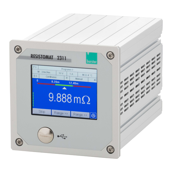
Page 18: Controls And Connections
Controls and connections Front panel Abbildung 2: Front view of the RESISTOMAT ® 2311 Item Description Touchscreen display User-definable function keys [F1] to [F3] Settings (“Configuration Main Menu”) Front panel USB service port Tabelle 1: Front panel items Note: You can choose to have the function keys and the icon displayed permanently or temporarily in measurement mode. -
Page 19: Rear Panel
Rear panel Abbildung 3: Rear view of the RESISTOMAT 2311 ® Item Description Power connection Power switch N/C including LED – not used Ethernet-based fieldbus ports (optional) PLC I/O signals External multiplexer port Measurement input; resistance and 0-10 V DC input for pyrometer Rear USB port (USB host port) Ethernet port Pt100 sensor connection... -
Page 20: Touch Operation
Touch operation The RESISTOMAT 2311 has a touchscreen display. You can tap or swipe the touchscreen to perform ® control actions. Touch control options Symbol used in the Action Description operating manual Tap the relevant point on the touchscreen with your finger. Swipe your finger downwards or upwards on the touchscreen. -
Page 21: Controls And Symbols
Controls and symbols The following control elements and icons occur repeatedly in the RESISTOMAT 2311: ® Symbol Meaning This icon opens the “Configuration Main Menu”. This icon always takes you back to the previous menu. Note: The settings you have made are usually applied. You can choose to tap on the scroll bar or swipe the scroll bar to reach other menu pages. -
Page 22: Grounding, Shielding And Connection Wiring
• Position signal lines away from power supply lines (in particular when laying cables near servomotors). • Preferably use the recommended burster test leads to connect test objects. The test lead must be connected in accordance with regulations and must not be exposed to mechanical disturbance or electrical interference. -
Page 23: Connections
Connections 4.6.1 PLC I/O signals NOTICE +24 V DC supply voltage Only connect devices that are designed for this supply voltage. The PLC control signals (inputs and outputs) are provided on the RESISTOMAT 2311 at the 25-way ® D-SUB port. The signals are isolated from the controller core and work with positive logic. An external 24 V DC supply is needed to operate the PLC outputs;... - Page 24 Signal name Configurable Meaning +24 VDC 24 V DC external supply voltage GND_EXT PLC-GND reference potential +24VDC_EXT IN_START Start/stop external measurement IN_AUTO RESISTOMAT stays in measurement mode IN_RES_STAT Reset the statistics IN_ACK_ERR Acknowledgment signal for OUT_ERROR IN_STROBE Adopt the measurement program no. from IN_PROG[] IN_PROG0 Bit 0 of measurement program no.
-
Page 25: Measurement Input
4.6.2 Measurement input Abbildung 6: Rx and pyrometer measurement input Meaning Measurement current I+ Measurement current I+ (sensor lead) External measurement start signal Measurement current I- (sensor lead) Measurement current I- Measurement input U+ 0…10 V DC pyrometer input External measurement start reference Measurement input U- Shield (ground) Housing... -
Page 26: Connection: Pt100 Sensor
Measurement input U- Shield/DGND Housing Tabelle 7: Pt100 pin assignment 4.6.4 External multiplexer port The 15-pin D-SUB HD socket is intended for connecting a burster-specific series 2600 multiplexer. Abbildung 8: Multiplexer port Meaning +5 VD EXT_CS_P DGND (connected to connector housing) -
Page 27: Usb Service Port
P100 for PLUS version) can communicate with each other via the USB service port. Use a USB-A plug to Micro-B connecting cable (burster part number 9900-K358, length 1.8 m) to connect to a PC USB port. The protocol specification for the USB service port is provided in a separate document: the “RESISTOMAT... -
Page 28: Ethernet Port
44). 4.6.8 Ethernet-based fieldbus interface (dual RJ-45) Details of the available Ethernet-based fieldbus interfaces are provided in a separate document (can be requested from info@burster.de or call +49 7224-645-0). 4.6.9 Device power plug IEC 60320 compliant C13/C14 cold connector plug. -
Page 29: Using The Device For The First Time
Using the device for the first time DANGER Electric shock hazard! Never switch on the RESISTOMAT 2311 if it shows signs of damage incurred in ® transit. Only ever use the RESISTOMAT 2311 under the conditions specified in ® this operating manual. Panel mounting NOTICE Excessive tightening torque may result in damage. -
Page 30: Panel Cutout
Item Description RESISTOMAT model 2311 ® Panel cutout Self-adhesive feet (remove before fitting) Instrument panel Mounting profiles (x4) Self-tapping Torx screws (x4) M4x20 Tabelle 9: Panel mounting terms 5.1.2 Panel cutout Abbildung 11: Panel cutout RESISTOMAT ® 2311 of 81... -
Page 31: User Language And Diagnostics
User language and diagnostics Immediately after power-up, the RESISTOMAT 2311 runs a self-test for about 5 seconds. During this ® self-test, you have the chance to change the user language or go directly to the “Diagnostics” menu (M44) if you wish. The set user language is displayed as a national flag in the top right of the screen during the self-test. -
Page 32: Device Configuration - "Configuration Main Menu
Device configuration – “Configuration Main Menu” The settings for the RESISTOMAT 2311 are configured via the “Configuration Main Menu” (M3). ® Once powered up, the RESISTOMAT 2311 enters measurement mode directly; to access the ® configuration settings for the device, touch anywhere on the touchscreen. The icon appears in the bottom right corner. -
Page 33: Basic Setup
Configuration Main Menu (M3) The following submenus are available in the “Configuration Main Menu” (M3): • Basic Setup Evaluation • • Calibration Program Selection • • Program Setup Copy Programs • Basic Setup The “Basic Setup” menu (M4) contains all the settings that do not relate specifically to measurement programs. -
Page 34: Function Key Definition
6.1.1 Function Key Definition The “Function Key Definition” menu (M20) lets you customize the three function keys displayed in measurement mode, and to select whether they are displayed permanently or only temporarily for 5 seconds. The following functions can be assigned: Item Meaning Not used... -
Page 35: Plc Outputs
6.1.2 PLC Outputs In the “Assignment of the PLC Outputs” menu (M21), you can customize which signals appear at certain PLC outputs. Pin 13 cannot be changed. You have the option to assign a different signal to pins 14 to 25 from the following: OUT_READY Ready signal for measurement OUT_MEAS_END... - Page 36 In measurement mode, tap anywhere on the touchscreen. The icon appears in the bottom right corner. to open the “Configuration Main Menu”. Tap the “Basic Setup” icon. Tap the “PLC Outputs” icon. To open the second page of the menu, tap the bottom of the scroll bar. Tap the name of the pin that you wish to reassign.
-
Page 37: Plc Inputs
6.1.3 PLC Inputs In the “Assignment of the PLC Inputs” menu (M22), you can customize which signals are assigned to certain PLC inputs. You cannot change the settings for pins 3, 8 to 10 and 12. You have the option to assign a different signal to pins 4 to 7 and 11 from the following: Signal Description IN_AUTO... -
Page 38: Access Permissions
6.1.4 Access Permissions You can make the following settings in the “Access Permissions” menu (M23): • Define/change a master password • Specify access levels for master/user Define/change a user password Block/unblock access by DigiControl. • • Enable/disable password protection • Factory-set master password: 2609 Factory-set user password:... -
Page 39: Blocking/Unblocking Access By The Digicontrol Pc Software
• Data Logger • Calibration After entering the master password, tap “Password Protection” to enable this option. Tap “Access Levels”. Select the access levels that you want to lock. to return to the “Access Permissions” menu. 6.1.4.3 Blocking/unblocking access by the DigiControl PC software In the “Access Permissions”... -
Page 40: Lcd Settings
6.1.6 LCD Settings In the “LCD Settings” menu (M25) you can set the brightness of the touchscreen display in 10 levels. In measurement mode, tap anywhere on the touchscreen. The icon appears in the bottom right corner. to open the “Configuration Main Menu”. Tap the “Basic Setup”... -
Page 41: Language
6.1.8 Language In the “Language Selection” menu (M27) you can set the user language for the RESISTOMAT 2311. ® The following 5 languages are available: Italian • German • • English • Spanish French • In measurement mode, tap anywhere on the touchscreen. The icon appears in the bottom right corner. -
Page 42: Usb Interface Parameters
2311 as a virtual COM port. The drivers needed for this ® port are installed together with the DigiControl PC software. If you want to use PC communication without the DigiControl PC software, you can download the necessary drivers from www.burster.com). Parameters in the “Interface Setup (USB/Ethernet)” menu (M37) -
Page 43: Ethernet Interface Parameters
6.1.9.2 Ethernet interface parameters Parameters in the “Ethernet Interface (UDP/IP)” menu (M38) DHCP Enabled / disabled When DHCP (Dynamic Host Configuration Protocol) is enabled, the RESISTOMAT 2311 is assigned an IP address, subnet mask and ® gateway by the DHCP server. IP address Enter the IP address for the RESISTOMAT 2311 here. -
Page 44: Usb Memory
6.1.10 USB Memory When data logging on a USB flash drive is enabled, an entry with result values is made in a file with each measurement. If you have connected a USB stick to the rear USB port on the RESISTOMAT 2311, the ®... -
Page 45: Diagnostics
File structure – HEADER Note: The “HEADER” is created just once when the file is created, but it is not checked again for plausibility. The “HEADER” contains the following information: In measurement mode, tap anywhere on the touchscreen. The icon appears in the bottom right corner. -
Page 46: Order Sheet
“Temperature too high for 1 A • • measurement” The “Service Login” menu is password protected and reserved for employees of burster präzisionsmesstechnik gmbh & co. kg. In measurement mode, tap anywhere on the touchscreen. The icon appears in the bottom right corner. -
Page 47: Ethercat Settings (Option)
6.1.13 EtherCAT settings (option) Abbildung 13: Note: The “EtherCAT” menu (M32) only exists if your RESISTOMAT ® 2311 is equipped with option Vxxx1. Abbildung 14: Abbildung 15: “Missing screenshot” Parameters in the “EtherCAT” menu (M32) Abbildung 16: 6.1.14 PROFINET settings (option) Note: The “PROFINET”... -
Page 48: Ethernet/Ip Settings (Option)
Name of station The station name assigned by the PROFINET host. IP address Assigned IP address Note: This parameter cannot be changed in the RESISTOMAT 2311. ® Subnet mask Assigned subnet mask Note: This parameter cannot be changed in the RESISTOMAT 2311. - Page 49 Note: The gateway address cannot be changed by the user if BOOTP or DHCP is selected for the IP configuration mode. Tabelle 17: EtherNet/IP menu parameters Note: Details of the EtherNet/IP interface are provided in a separate document: the RESISTOMAT 2311 EtherNet/IP manual on the product page.
-
Page 50: Evaluation
Evaluation In the “Evaluation” menu (M5), you can display the analysis/counters of the various measurement evaluations: Data Logger, Comparator, Max / Min and Cooling Curve. 6.2.1 Data Logger The individual parameters and measured values of the data logger records stored on the device are displayed in the “Data Logger Evaluation”... -
Page 51: Cooling Curve
1. To open the “Evaluation” menu from measurement mode, tap anywhere on the touchscreen. The icon appears in the bottom right corner. 2. Tap to open the “Configuration Main Menu”. 3. Tap the “Evaluation” icon. 4. Tap the “Max / Min” icon. 5. -
Page 52: Calibration
Calibration Program Selection In the “Program Selection” menu (M7) you can select the measurement program number and give the program a name. Program number selection Select the measurement program for which you wish to make specific settings. The currently active measurement program is always displayed in the top left corner. Naming the program Specify a name for the selected measurement program. -
Page 53: Program Setup Menu
Program Setup menu The “Program Setup” menu (M8) contains all the settings that relate specifically to measurement programs. You can edit or view the following settings and information in the “Program Setup” menu (M8): Measurement Method Comparator Data Lo Max / Min Temp. -
Page 54: Range Selection
6.5.1.1 Range selection In the “Range selection” row, you can switch between manual and automatic measuring range selection. In the “Automatic” setting, the device automatically selects the optimum measuring range for the measured value. Automatic range selection only works with the purely ohmic test object setting. “Test object”“R”. -
Page 55: Minimum And Maximum Range
6.5.1.3 Minimum and maximum range If automatic range selection is selected, you can use the “Minimum range” and “Maximum range” rows to set a lower or upper limit for the measuring range that the device selects. In measurement mode, tap anywhere on the touchscreen. The icon appears in the bottom right corner. -
Page 56: Type Of Measurement
DANGER Before starting any measurement, make sure that the test object is free of any external voltage (e.g. mains voltage, voltage generated by a rotating motor, etc.) Take care when handling inductive test objects. The physics are such that potentially lethal voltages can occur when the test current is disconnected. •... -
Page 57: N Measurements
6.5.1.6 N measurements In the “N measurements” row, you can define which number measured value is displayed with the “N measurements” measurement type. If another measurement type is selected, this row is grayed out. In measurement mode, tap anywhere on the touchscreen. The icon appears in the bottom right corner. -
Page 58: Averaging
6.5.1.8 Averaging The method by which averaging is performed is defined in the “Averaging” row. Renew Means that if an averaging value of 10 is entered, a new value (mean value) only appears on the display after 10 measurements. Sliding Means that if an averaging value of 10 is entered, after the start or after a measurement error occurs, a new value (mean value) only appears on the display after 10 measurements –... -
Page 59: Limiting
6.5.1.10 Limiting 6.5.1.11 Conversion You can define the conversion level in this row. The device has a very fast A/D converter, with settings for 4 conversion time levels. The conversion times for the individual levels depend on the set measuring range and the selected resolution. -
Page 60: Test Current
6.5.1.13 Test current In this row, depending on the set measuring range, you can switch between the high or low test current settings. Depending on the environment at the test location, strong electromagnetic fields can cause the displayed resistance value to fluctuate. This can be remedied by averaging several measurements or increasing the test current to achieve a higher signal-to-noise ratio. -
Page 61: If Error
6.5.1.14 If error This row defines how to proceed in a continuous measurement after a measurement error. If a measurement type other than “continuous” is set, the “If error” row is grayed out. Continue measuring The measurement error has no effect on the continuous measurement, which is continued. -
Page 62: Comparator
6.5.2 Comparator All settings relating to the evaluation of measured values are made in the “Comparator” menu (M51). The device has a 2-way and 4-way comparator with switching outputs for performing classification and selection. To open the “Comparator” menu from measurement mode, tap anywhere on the touchscreen. icon appears in the bottom right corner. -
Page 63: Limit Values
6.5.2.2 Limit values In this row, you can change the setting between 2 and 4 limit values. This determines the number of selection levels. 2 Limits 4 Limits 6.5.2.3 If error In this row, you can set how the device deals with an error in a comparator evaluation. None No action. -
Page 64: Limit Values
6.5.2.4 Limit values <<, <, >, >> In these rows, you define the limit values depending on whether 2 or 4 selection levels are set. In measurement mode, tap anywhere on the touchscreen. The icon appears in the bottom right corner. to open the “Configuration Main Menu”. -
Page 65: Data Logger
6.5.3.1 Data Logger In this row, you can activate or deactivate the internal data logger function. In measurement mode, tap anywhere on the touchscreen. The icon appears in the bottom right corner. to open the “Configuration Main Menu”. Tap the “Program Setup” icon. Tap the “Data Logger”... -
Page 66: Nth Value
6.5.3.3 Nth value In this row, you can define the nth measured value that is recorded in the data logger. To do this, “Nth value” must be selected under “Filter”. Otherwise the row is grayed out. In measurement mode, tap anywhere on the touchscreen. The icon appears in the bottom right corner. -
Page 67: Delta R
6.5.3.5 Delta R You can define an ohmic delta value in this row. As soon as the delta between the last and the current measured value >= the Delta R value, this measured value is recorded. This requires “Delta R” to be selected under “Filter”. Otherwise the row is grayed out. In measurement mode, tap anywhere on the touchscreen. -
Page 68: Free Memory
6.5.3.7 Free memory This row shows how much free memory the active measurement program still has. One space corresponds to one measured value. No settings can be made here. 6.5.3.8 Delete In this row, you can delete the data logger recording of the active program and clear the memory. In measurement mode, tap anywhere on the touchscreen. -
Page 69: Temperature Compensation
6.5.5 Temperature compensation The temperature compensation parameters are set in the “Temp. Comp.” menu (M54). Enabling temperature compensation changes the display value. The value displayed is the resistance that a device made of this material would have if its temperature were e.g. 20 °C. The conversion in the device is carried out as follows: ����... -
Page 70: Source
6.5.5.2 Source In this row, you specify how the real temperature is measured/set. Three sources can be selected. Manual A static, manually entered temperature value is specified to the RESISTOMAT model ® 2311 for temperature compensation. Pt100 The temperature is measured via a Pt100 temperature sensor (f.e. model 2392-V001) and read in at the corresponding input. -
Page 71: Coefficient
The reference temperature, i.e. the standard temperature value for temperature compensation, is defined in this row. In measurement mode, tap anywhere on the touchscreen. The icon appears in the bottom right corner. to open the “Configuration Main Menu”. Tap the “Program Setup” icon. Tap the “Temp. -
Page 72: Pt100
Tap the “Program Setup” icon. Tap the “Temp. Comp” icon. Tap the “User Coeff.” row. Enter the desired value using the keypad and confirm with [OK]. 6.5.6 Pt100 The “Pt100” menu (M55) shows the formula on which the calculation of the temperature via the Pt100 sensor is based. -
Page 73: Measured Value Display
6.5.8 Measured Value Display In the “Meas. Val. Disp.” menu (M57), you can set how the measured value is displayed in measurement mode. The RESISTOMAT model 2311 can display the measured value in three different formats: ® The measured value is displayed as an ohmic decimal numerical value. The measured value is displayed as a percentage deviation from a predefined reference value. -
Page 74: Usb Memory
Note: Upon activation of the cooling curve mode, the RESISTOMAT model 2311 automatically ® switches the test object to inductive and activates the time constant Z0. If necessary, this setting can be adjusted to Z1, Z2 or Z3. Upon deactivation of the cooling curve mode, the setting of R for the test object and the time constant setting must be made manually. - Page 75 Note: Please note that when the “IN_AUTO” control input is activated, the “PLC Test” menu (M60) will close automatically and the RESISTOMAT 2311 will switch to measurement mode. ® In measurement mode, tap anywhere on the touchscreen. The icon appears in the bottom right corner.
-
Page 76: Copy Programs
Copy Programs In the “Copy Programs” menu (M9), you can copy measurement programs or initialize programs with a set of initial settings. 6.6.1 Copying a measurement program or measurement method If you want to re-use most of the settings in a measurement program, you can make a copy of the measurement program. -
Page 77: Display In Measurement Mode
In measurement mode, tap anywhere on the touchscreen. The icon appears in the bottom right corner. to open the “Configuration Main Menu”. Tap the “Copy Programs” icon. Tap [From target] to select the first destination program and then [To target]to select the last destination program in which you want to initialize the data. -
Page 78: Full View Of Measured Values
Full view of measured values Program name Program number Test current Limiting if active Temperature value Measuring range source selection & & measured value active measuring range Measurement Error status Measurement type: Range selection continuous or single Test object, R-Z3 Footer with function key assignment Error status display... -
Page 79: Customer Services For Your Resistomat ® 2311
+49 7224 645-54, or email service@burster.de (in Germany only). In other countries please contact your local representative (see also www.burster.com). Technical data Please refer to the data sheet for the technical specifications. You can obtain the latest data sheet and... -
Page 80: Accessories Available
Accessories available Please refer to the data sheet for details of the accessories available. You can obtain the latest data sheet and additional information on the RESISTOMAT 2311 on the product page or simply use the QR ® code below: Abbildung 22: QR code for the RESISTOMAT ®... -
Page 81: Disposal
Disposal Battery disposal In Germany, the end user is legally obliged to return all used batteries, and it is illegal to dispose of batteries in the household waste. This law may also affect you as purchaser of the instrument described here. Please dispose of your used batteries properly and in accordance with national statutory regulations.
Need help?
Do you have a question about the RESISTOMAT 2311 and is the answer not in the manual?
Questions and answers