Table of Contents
Advertisement
Quick Links
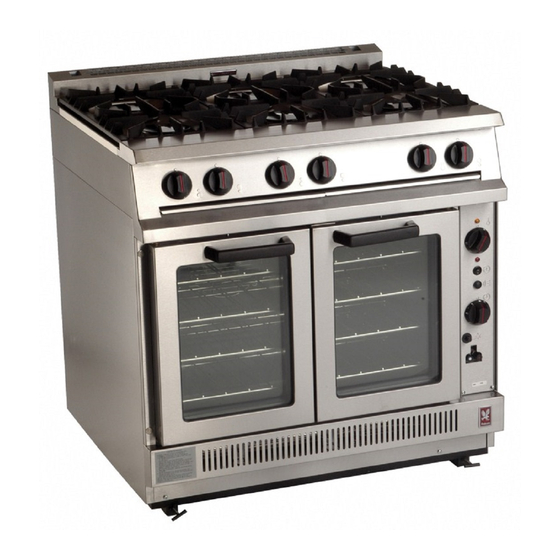
G2102 FORCED
CONVECTION OVEN RANGE
G2112 FORCED
CONVECTION OVEN (May 2010)
INSTALLATION and SERVICING INSTRUCTIONS
These appliances must be installed and serviced by a competent person as stipulated by the Gas Safety
(Installation & Use) Regulations.
IMPORTANT
The installer must ensure that the installation of the appliance is in conformity with these instructions and National
Regulations in force at the time of installation. Particular attention MUST be paid to –
BS7671 I.E.E. Wiring Regulations
Gas Safety (Installation & Use) Regulations
Local and National Building Regulations
Detailed recommendations are contained in Institute of Gas Engineers published documents :
IGE/ UP/ 1, IGE/ UP/ 2
BS6173 and BS5440
The appliances have been CE-marked on the basis of compliance with the Gas Appliance Directive, EMC and Low
Voltage Directive for the Countries, Gas Types, Gas Pressures and voltages as stated on the Data Plate.
WARNING - TO PREVENT SHOCKS, ALL APPLIANCE MUST BE EARTHED
On completion of the installation, these instructions should be left with the Engineer-in-Charge for reference during
servicing. Further to this, The Users Instructions should be handed over to the User, having had a demonstration of
the operation and cleaning of the appliance.
IT IS MOST IMPORTANT THAT THESE INSTRUCTIONS BE CONSULTED BEFORE INSTALLING AND COMMISSIONING
THIS APPLIANCE. FAILURE TO COMPLY WITH THE SPECIFIED PROCEDURES MAY RESULT IN DAMAGE OR THE NEED
FOR A SERVICE CALL.
PREVENTATIVE MAINTENANCE CONTRACT
In order to obtain maximum performance from this unit we would recommend that a Maintenance Contract be
arranged with SERVICELINE. Visits may then be made at agreed intervals to carry out adjustments and repairs. A
quotation will be given upon request to the contact numbers below.
Falcon Foodservice Equipment
Head Office and Works
Wallace View, Hillfoots Road, Stirling. FK9 5PY. Scotland.
Serviceline
PHONE : 01438 363 000
WEEE Directive Registration No. WEE/DC0059TT/PRO
At end of unit life, dispose of appliance and any replacement parts in a safe manner, via a
licensed waste handler.
Units are designed to be dismantled easily and recycling of all material is encouraged
whenever practicable.
Electricity At Work Regulations
Health And Safety At Work etc. Act
Fire Precautions Act
T100732 Ref.5
Advertisement
Table of Contents


Need help?
Do you have a question about the G2102 and is the answer not in the manual?
Questions and answers