
Subscribe to Our Youtube Channel
Related Manuals for Generac Mobile MMG25IF4


Summary of Contents for Generac Mobile MMG25IF4
- Page 1 Owner’s Manual Diesel Generator MMG25IF4 • MMG35DF4 • MMG45IF4 • MMG55DF4 01306 For technical assistance contact: www.generacmobileproducts.com Technical Support 1-800-926-9768 SAVE THIS MANUAL FOR FUTURE REFERENCE...
- Page 2 Engine and generator serial numbers are located on separate Unit Serial No. data plates affixed to the engine and generator respectively. When contacting a Generac Mobile Authorized Service Dealer (GMASD) about parts and service, always supply the complete Engine Model No.
-
Page 3: Table Of Contents
Table of Contents Section 1: Introduction and Safety Engine Monitoring .............22 Power Zone Controller Information Displays, Func- Introduction ..............1 tions, and Reset ............22 Read This Manual Thoroughly ........1 Voltage Selector Switch ..........22 How to Obtain Service ..........1 Safety Rules ..............1 Section 3: Operation General Hazards ............2 Pre-start Checklist .............23... - Page 4 Daily Walk Around Inspection ........35 Belt Tensioners ............35 General Maintenance ..........35 Engine Oil Recommendations ........36 Coolant Recommendation ........36 Basic Maintenance Schedule ........37 Engine Break-In Requirements—Isuzu ....39 Engine Break-In Requirements—John Deere ..39 Resetting Maintenance Alarms ........ 39 Exhaust Filter Service Requirements ......
-
Page 5: Section 1: Introduction And Safety
Section 1: Introduction and Safety Introduction Safety Rules Thank you for purchasing a Generac Mobile product. This The manufacturer cannot anticipate every possible unit has been designed to provide high performance, circumstance that might involve a hazard. The warnings in... -
Page 6: General Hazards
Introduction and Safety General Hazards WARNING Risk of injury. Do not operate or service this machine DANGER if not fully alert. Fatigue can impair the ability to Asphyxiation. Running engines produce carbon operate or service this equipment and could result in monoxide, a colorless, odorless, poisonous death or serious injury. -
Page 7: Electrical Hazards
Introduction and Safety Electrical Hazards Lifting Hazards DANGER WARNING Electrocution. In the event of electrical accident, Personal injury. Failure to properly connect immediately shut power OFF. Use non-conductive lifting cables, chains, or straps could result in implements to free victim from live conductor. Apply death, serious injury, or property damage. -
Page 8: Battery Hazards
Introduction and Safety Battery Hazards Engine Safety Internal combustion engines present special hazards DANGER during operation and fueling. Failure to follow the safety guidelines described below could result in severe injury or Electrocution. Do not wear jewelry while death. Read and follow all safety alerts described in the working on this equipment. -
Page 9: Starting The Unit
Introduction and Safety reuse the nylon locking nuts. Tighten the bolts to • The area immediately surrounding the unit should 80–109 ft-lb (108–148 Nm). be dry, clean, and free of debris. • If the unit is equipped with a frame grounding stud, follow any local, state, and National Electrical Code (NEC) guidelines when connecting. -
Page 10: Safe Towing Techniques
However, NHTSA cannot become involved in an individual problem between you, your GMASD, or Generac Mobile. To contact NHTSA, you may either call the Auto Safety Hotline toll-free at 1-888-327-4236 (TTY:1-800-424-9153), go to http://www.safercar.gov;... -
Page 11: Safety And Operating Decals
Introduction and Safety Safety and Operating Decals This unit features numerous safety and operating decals. Replace any missing or hard-to-read decals and use care These decals provide important operating instructions and when washing or cleaning the unit. Decal part numbers warn of dangers and hazards. - Page 12 Introduction and Safety 00808 Figure 1-4. Exterior Decals Owner’s Manual for Mobile Generator...
- Page 13 Introduction and Safety Generator can automatically start which can cause serious injury. Disconnect battery before servicing. Der Generator kann automatisch anspringen und schwere Verletzungen verursachen. Vor der Instandsetzung die Batterieverbindungen lösen. El generador puede arrancar automáticamente, lo que puede causar graves lesiones.
- Page 14 Introduction and Safety STARTING THE GENERATOR DAS STARTEN DES GENERATORS COMIENZO DEL GENERADOR COMMENCEMENT DU GÉNÉRATEUR 1. CONTROL POWER 2. PUSH ENGINE SWITCH “ON” START “I” Read and understand the supplied operator’s manual before operating this machine. Failure to do so increases the risk of injury to yourself or others.
-
Page 15: Section 2: General Information
Section 2: General Information Specifications Description Unit of Measure MMG25IF4 MMG35DF4 Engine ® ® Make — Isuzu John Deere EPA Tier — Fuel consumption—100%: Prime gph (Lph) 2.1 (7.8) 2.9 (11.0) Battery voltage V (quantity per unit) 12 (1) 12 (1) - Page 16 General Information Description Unit of Measure MMG25IF4 MMG35DF4 Engine Make — Isuzu John Deere EPA Tier — Fuel consumption—100%: Prime gph (Lph) 3.3 (12.5) 3.9 (14.8) Battery voltage V (quantity per unit) 12 (1) 12 (1) Battery rating Generator Three phase—standby...
-
Page 17: Unit Dimensions
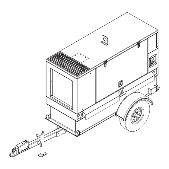
General Information Unit Dimensions 008083 Figure 2-1. Unit Dimensions Skid Mounted 39 in (0.99 m) 95 in (2.41 m) 65 in (1.65 m) Trailer Mounted 58 in (1.45 m) 152 in (3.81 m) 83 in (2.11 m) Owner’s Manual for Mobile Generator... -
Page 18: Unit And Serial Number Locations
General Information Unit and Serial Number Locations Figure 2-2 to locate the unit ID tag (A) (located behind breaker door beneath breakers) and vehicle identification number (VIN) tag (B). Important information such as the unit model number, serial number, VIN, and tire loading information are listed on these tags. -
Page 19: Component Locations
General Information Component Locations Exterior 008881 Figure 2-3. Exterior Components Engine exhaust Breaker panel access door Radiator access panel Coolant and oil drain Unit lift point Lug box access door Fuel fill port Receptacle panel Side marker M Emergency stop switch Rear stabilizer mount Tail light (2 locations) Tie-down point... -
Page 20: Connection Panel
General Information Connection Panel 01882 Figure 2-4. Connection Panel Components Main circuit breaker Ground connection lug Panel light Connection lugs 50 A circuit breaker (3 locations) Cam lock receptacle (5 locations) (if equipped) Service lights switch 120/240 V twist-lock outlets 20 A circuit breaker (2 locations) M Connection for optional equipment Inlet Lug door safety switch... -
Page 21: Control Panel
General Information Control Panel 009643 Figure 2-5. Control Panel Components Power Zone controller Regen switch (if equipped) Panel light Engine idle Voltage selector switch Control power switch Owner’s Manual for Mobile Generator... -
Page 22: Genset Controller
General Information Genset Controller Figure 2-6. The genset controller is an auto start screen will show the fault that caused the shut down. The controller that monitors the unit and indicates operational fault condition must be resolved to resume unit operation. status and fault conditions. -
Page 23: Controller Features And Functions
General Information Controller Features and Functions Home Screen The home screen is the controller’s default screen and These buttons are used to enter the various operator automatically displays after the controller is powered up screens from any other screen. The operator screens and the unit management software is loaded. -
Page 24: Maintenance Screens
General Information Voltage Adjust Screen • Coolant Temp: Displays engine coolant temperature. Current coolant temperature displays The unit automatically fine tunes voltage upon start-up directly below the gauge at all times. The gauge after the output voltage is selected and the unit is started. displays coolant temperature between 150–250 °F Voltage Selector Switch. -
Page 25: Engine Tab
General Information Engine Tab Alarms Tab engine contains maintenance The alarms tab displays warnings, electrical trip, instrumentation data gathered from the engine. Above shutdown alarms, and any engine diagnostic trouble the engine analog meters is a row of alarm icons. Each codes (DTC) that are occurring or have occurred. -
Page 26: Input/Output Tab
General Information To scroll down within the event log, press the ENTER () SITE GENSET 7741 \ 7740 button. The scroll bar will activate and change to blue. 480V/277V 3-Phase 07:10 Return Delay 10:00:00 Total Generator Press the ▲ or buttons to scroll up or down in the event kWh+ log. -
Page 27: Section 3: Operation
Section 3: Operation Pre-start Checklist Verify all electrical connections at the connection lugs, if equipped, are tight and wired correctly. All items in the pre-start checklist must be completed Verify the voltage selector switch is set to the desired before starting the unit. -
Page 28: Auto (Remote) Starting The Unit
Operation the generator, depending on the type of engine governing used. Stop Mode 11. If all wiring connections have been made correctly, Time to Empty 15 hr switch the main circuit breaker to ON (I), and then 100 110 Full 3 PHASE 0.0 kW add any loads attached to the receptacles by... -
Page 29: Wet Stacking
Operation D E F 002806 Figure 3-3. Remote Start Terminal Block Wet Stacking The unit is powered by a diesel engine. Diesel engines are susceptible to wet stacking if lightly loaded. Wet stacking occurs when an engine is run at less than 30% of its full load capacity, causing unburned fuel to 008597 accumulate in the exhaust system. -
Page 30: Using A Booster Battery Or Charger (If Equipped)
Operation Using a Booster Battery or Charger (if Parallel: equipped) • Amps = Twice as a single battery • Volts = Same as single battery WARNING Explosion. Batteries emit explosive gases while charging. Keep fire and spark away. Wear protective gear when working with batteries. -
Page 31: Generator Output Connections
Operation Generator Output Connections ground when it is shipped from the factory. The bonding plate must be removed when the generator is used as a standby power source. DANGER Electrical backfeed. Use only approved switchgear to isolate generator from the normal power source. Failure to do so will result in death, serious injury, and equipment damage. -
Page 32: Using The Voltage Selector Switch
Operation Fine Voltage Adjustment plugs into the cam lock receptacles. Secure the connection by rotating the plug ½ turn to the right. Voltage Adjust Screen for information on screen display. Manual Mode Black Voltage Adjust Blue - Press , voltage will begin flashing - Use arrows to adjust voltage N (Neutral) -
Page 33: Achieving 240V Three-Phase In 208V Three-Phase (Parallel Low Wye) Configuration
Operation Achieving 240V Three-Phase in 208V access to password entry. The left most pound sign should change to 0. Three-Phase (Parallel Low Wye) 11. Press ▲, ►, ▼, or ◄ to enter the password 4444 if Configuration applicable. Press . 12. -
Page 34: Main Circuit Breaker
480/277V three-phase, voltage at the two GFCI regeneration. receptacles is 139 volts and the voltage at the three twist- lock receptacles is 240/139 volts. Generac Mobile does NOTE: Always park the unit in a safe location for not recommend using the receptacles in the 480V elevated exhaust temperatures and check for adequate position. -
Page 35: Enable Exhaust After-Treatment Cleaning
Operation Enable Exhaust After-Treatment Cleaning When the unit is used as a standby power supply, it must be equipped with a transfer switch that isolates it from the If the environment no longer requires the exhaust after- utility’s distribution system. A transfer switch is designed treatment cleaning function to be disabled, and there are to transfer electrical loads from the normal power source no alarms present on the SCR status screen, the auto... -
Page 36: Set The Controller Clock
Operation Setting Up a Daily Scheduled Run any changes and return to the maintenance screen, press and hold O for five seconds. 1. Enable the scheduler. 2. Set RUN mode to Weekly. Set the Controller Clock 3. Set load to preferred method. The schedule runs based on the time set in the controller 4. -
Page 37: Emergency Stop Switch
Operation Emergency Stop Switch Towing the Unit CAUTION WARNING Equipment Damage. The emergency stop switch is Personal injury. Trailer must be securely coupled to the not to be used to power down the unit under normal hitch with the chains correctly attached. Uncoupled or operating circumstances. -
Page 38: Lifting The Unit
Operation 4. Attach any slings, chains or hooks directly to the central lift point. 007620 Figure 3-11. Lug Sequence 01035 Figure 3-12. Lifting Points WARNING Tying Down the Unit Property or Equipment Damage. Tighten wheel lug nuts after first 50 miles to factory specifications. When securing the unit for transportation, verify the Failure to do so could result in death, serious injury, equipment being used to fasten the unit is in good... -
Page 39: Section 4: Maintenance
• Verify the control power switch is turned OFF (O). extends engine/equipment life. Generac Mobile recom- mends that all maintenance work be performed by a • Verify the circuit breakers are turned OFF (O). GMASD. Regular maintenance, replacement, or repair of •... -
Page 40: Engine Oil Recommendations
Maintenance including special operating conditions such as a change in season or climate. – DO NOT start the unit if the engine oil level is below the add mark on the dipstick. – Normal operating level is between the dipstick FULL and ADD marks. -
Page 41: Basic Maintenance Schedule
Checking Generator Drive Plate Torque Replace fan belt MMG25IF4 only. MMG45IF4 only. If the unit is operated in a harsh environment or fuel quality is questioned, replace every 250 hours instead of every 500 hours. Owner’s Manual for Mobile Generator... - Page 42 Maintenance Basic Maintenance Schedule—John Deere Engine First 100 Hrs. Every 250 Every 500 Every 2000 Every 6000 Item Daily (Break-in Hrs. Hrs. Hrs. Hrs. Required Period) Check engine oil level Check engine coolant level Check fuel level Check tire pressure ...
-
Page 43: Engine Break-In Requirements-Isuzu
Maintenance Engine Break-In Requirements— 4. Press to move the cursor (blue highlighted text) down to the maintenance group. Isuzu 5. Press ► to access the sections. Press to high- NOTE: The EPA final Tier 4 Isuzu engines have an light the maintenance section. -
Page 44: Jack Maintenance
Maintenance 3. Tighten each drive plate bolt as shown below. Grease Unit Torque: ft-lb (Nm) MMG25IF4 30 (40) MMG35DF4 40 (54) MMG45IF4 30 (40) MMG55DF4 40 (54) 4. Install generator fan guard. 002824a 5. Connect battery. Jack Maintenance The following procedures should be performed annually. -
Page 45: Section 5: Troubleshooting
Section 5: Troubleshooting General Troubleshooting This information is intended to be a check or verification information. Procedures that require in-depth knowledge for simple causes that can be located and fixed. It does or skills should be performed by a GMASD. not cover all types of problems. - Page 46 Troubleshooting This page intentionally left blank. Owner’s Manual for Mobile Generator...
-
Page 47: Section 6: Wiring Diagrams
Section 6: Wiring Diagrams 3-Position AC Box 90580_ORG_10.14.14 Owner’s Manual for Mobile Generator... -
Page 48: 3-Position Ac Box
Wiring Diagrams 3-Position AC Box 90632_ORG_01.14.15 Owner’s Manual for Mobile Generator... -
Page 49: 4-Position Ac Box
Wiring Diagrams 4-Position AC Box 90581_ORG_10.14.14 Owner’s Manual for Mobile Generator... -
Page 50: 4-Position Ac Box
Wiring Diagrams 4-Position AC Box 90633_ORG_01.20.15 Owner’s Manual for Mobile Generator... -
Page 51: Receptacles
Wiring Diagrams Receptacles 3 POS BLK GND STUD BRKR BRKR BRKR 20 20 GFCI1 GFCI2 2 POS BLK GN/YL GN/YL GN/YL 90582_ORG_08.18.14 Engine Heater BLOCK HEATER WHITE WHITE SPLICE WHITE 28407 66080 RECEPTACLE 68635 50125 GREEN GREEN TERMINAL 65006 SPLICE BLACK BLACK BLACK... -
Page 52: Wiring Buck (If Equipped)
Wiring Diagrams Wiring Buck (If Equipped) TO 120V TO 120V BREAKERS BREAKERS VOLTAGE RELAY VOLTAGE RELAY POWER POWER RELAY RELAY 3 POS BLK 3 POS BLK BUCK BUCK XFMR XFMR 90583_ORG_08.18.14 Power Zone PMG 1 2 3 4 5 6 7 REMOVE JUMPERS FOR PMG 90589_ORG_08.18.14 Owner’s Manual for Mobile Generator... -
Page 53: Power Zone Control Box
Wiring Diagrams Power Zone Control Box 90540_D_06.15.15 Owner’s Manual for Mobile Generator... -
Page 54: Trailer Lights
Wiring Diagrams Trailer Lights TRAILER PLUG RIGHT AMBER MARKER LAMP LEFT AMBER MARKER LAMP RIGHT LEFT MARKER MARKER LAMP LAMP STOP-TURN SIGNAL STOP-TURN LAMP SIGNAL (RIGHT) LAMP (LEFT) LICENSE PLATE LAMP 90584_ORG_10.02.14 Owner’s Manual for Mobile Generator... -
Page 55: Brake Wiring
Wiring Diagrams Brake Wiring SPLICE SPLICE SPLICE SPLICE SPLICE SPLICE SPLICE SPLICE SPLICE SPLICE SPLICE SPLICE SPLICE SPLICE 90286_E_03.18.14 Owner’s Manual for Mobile Generator... -
Page 56: 12-Volt Battery Charger
Wiring Diagrams 12-Volt Battery Charger WHITE RECEPTACLE BATTERY 65285 66212 CHARGER GREEN 66212 BLACK BREAKER 15568 TERMINALS 65003 12 V BATTERY 90593_B_09.19.16 Power Zone Low Oil Level (If Equipped) LEVEL 90595_ORG_10.31.14 Owner’s Manual for Mobile Generator... - Page 57 Wiring Diagrams This page intentionally left blank. Owner’s Manual for Mobile Generator...
- Page 58 Wiring Diagrams This page intentionally left blank. Owner’s Manual for Mobile Generator...
- Page 60 ©2020 Generac Mobile Products, LLC All rights reserved. Generac Mobile Products, LLC Specifications are subject to change without notice. 215 Power Drive, Berlin, WI 54923 GeneracMobileProducts.com │800-926-9768 │920-361-4442 No reproduction allowed in any form without prior written consent from Generac Mobile Products, LLC.
Need help?
Do you have a question about the MMG25IF4 and is the answer not in the manual?
Questions and answers