
Subscribe to Our Youtube Channel
Related Manuals for Generac Mobile MDE570


Summary of Contents for Generac Mobile MDE570
- Page 1 Owner’s Manual Diesel Generator MDE570P For technical assistance contact: www.generacmobileproducts.com Technical Support 1-800-926-9768 SAVE THIS MANUAL FOR FUTURE REFERENCE...
- Page 2 Unit Serial No. Engine and generator serial numbers are located on separate data plates affixed to the engine and generator. When contacting a Generac Mobile Authorized Service Engine Model No. Dealer (GMASD) about parts and service, supply the complete model number and serial number of the unit.
-
Page 3: Table Of Contents
Table of Contents Section 1: Introduction and Safety Cold Weather Starting Aids (If Equipped) ..............25 Introduction ..............1 Component Locations ..........25 Read This Manual Thoroughly ........1 Recommendations ............25 How to Obtain Service ..........1 Safety Rules ..............1 Section 3: Operation Safety Symbols and Meanings ........1 Overview ..............27 General Hazards ............2 Prestart Checklist ............27... - Page 4 Section 4: Maintenance Emissions Information ..........41 Maintenance ............... 41 Daily Walk Around Inspection ........41 General Maintenance ..........41 Fuel Recommendations ..........42 Adding Fuel ..............42 Engine Oil Recommendations ........42 Commercial Oils ............42 Aftermarket Oil Additives .......... 43 Oil analysis ..............
-
Page 5: Section 1: Introduction And Safety
Section 1: Introduction and Safety Introduction Safety Rules Thank you for purchasing a Generac Mobile product. The manufacturer cannot anticipate every possible This unit has been designed to provide high circumstance that might involve a hazard. The warnings performance, efficient operation, and years of use when in this manual, and on tags and decals affixed to the unit maintained properly. -
Page 6: General Hazards
General Hazards WARNING Risk of injury. Do not operate or service this machine DANGER if not fully alert. Fatigue can impair the ability to Asphyxiation. Running engines produce carbon operate or service this equipment and could result in monoxide, a colorless, odorless, poisonous death or serious injury. -
Page 7: Electrical Hazards
Electrical Hazards Lifting Hazards DANGER WARNING Electrocution. In the event of electrical accident, Personal injury. Failure to properly connect immediately shut power OFF. Use non-conductive lifting cables, chains, or straps could result in implements to free victim from live conductor. Apply death, serious injury, or property damage. -
Page 8: Battery Hazards
Battery Hazards DANGER Risk of fire. Allow fuel spills to completely dry DANGER before starting engine. Failure to do so will Electrocution. Do not wear jewelry while result in death or serious injury. working on this equipment. Doing so will (000174) result in death or serious injury. -
Page 9: Starting The Unit
However, NHTSA cannot become involved in an individual problem between you, your GMASD, or Generac Mobile. To contact NHTSA, you may either call the Auto Safety Hotline toll-free at 1-888-327-4236 (TTY:1-800-424- 9153), go to http://www.safercar.gov;... - Page 10 10000022505 DANGER GEFAHR PELIGRO DANGER BREATHING DIESEL ENGINE EXHAUST EXPOSES YOU TO CHEMICALS KNOWN TO THE STATE OF CALIFORNIA TO CAUSE CANCER AND BIRTH DEFECTS OR OTHER REPRODUCTIVE HARM. 1). ALWAYS START AND OPERATE THE ENGINE IN A WELL-VENTILATED AREA. 2).
- Page 11 Operator’s manual must be stored on machine. Replacement operator’s manual can be ordered through your local Generac distributor. Das Benutzerhandbuch muss an der Maschine aufbewahrt werden. Zur Bestellung von Ersatzhandbüchern wenden Sie sich bitte an Ihren Generac-Händler. El manual del operador debe guardarse en la máquina. Puede solicitar un manual del operador de reemplazo a través de su distribuidor local de Generac.
- Page 12 Operator’s manual must be stored on machine. Replacement operator’s manual can be ordered through your local Generac distributor. Das Benutzerhandbuch muss an der Maschine aufbewahrt werden. Zur Bestellung von Ersatzhandbüchern wenden Sie sich bitte an Ihren Generac-Händler. El manual del operador debe guardarse en la máquina. Puede solicitar un manual del operador de reemplazo a través de su distribuidor local de Generac.
-
Page 13: Section 2: General Information
Section 2: General Information Specifications Description Unit Of Measure MDE570P Engine — ® Make (Model) Perkins (2806F-E18TAG1) Rated Power Output—Prime hp (kW) 670 (500) Operating Speed 1,800 Fuel Consumption—100% Prime gph (L/hr) 33.0 (124.9) Fuel Consumption—75% Prime gph (L/hr) 24.7 (93.5) Fuel Consumption—50% Prime gph (L/hr) 16.8 (63.3) - Page 14 Description Unit Of Measure MDE570P 480/277 VAC kW/kVA (A) 500/625 (753) 600/346 VAC kW/kVA (A) 500/625 (602) 3Ø Prime: 208/120 VAC kW/kVA (A) 456/570 (1,584) 240/139 VAC kW/kVA (A) 456/570 (1,372) 480/277 VAC kW/kVA (A) 456/570 (686) 600/346 VAC kW/kVA (A) 456/570 (549) Weights Skid Mounted...
-
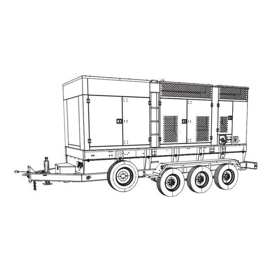
Page 15: Unit Dimensions
Unit Dimensions 01348 Figure 2-1. Unit Dimensions Skid Mounted 204.8 in (5.2 m) 73.0 in (1.9 m) 109.0 in (2.8 m) Trailer Mounted 260.0 in (6.6 m) 102.0 in (2.6 m) 118.8 in (3.0 m) Owner’s Manual for Mobile Generator... -
Page 16: Unit Id And Vin Tag Locations
Unit ID and VIN Tag Locations and 100% of its rated capacity. Appropriate generator sizing is determined by the anticipated load. The unit ID tag is located on the control Figure 2-2 panel face. The vehicle identification number (VIN) tag Load Management System (B) is located on the drivers side of the trailer tongue. -
Page 17: Component Locations-Unit Exterior
Component Locations—Unit Exterior 014004 Figure 2-3. Exterior Components Hot air/exhaust duct Tongue jack Radiator/coolant fill access panel Coolant drain Central lift point Engine oil drain Diesel exhaust fluid (DEF) fill port Link board access door DEF drain (not shown—unit underside) Generator access door Extended run fuel system (if equipped) 3-phase AC power distribution access door... -
Page 18: Component Locations-Unit Interior
Component Locations—Unit Interior 014005 Figure 2-4. Interior Components Diesel oxidation catalyst (DOC) and Diesel particulate Link board panel filter (DPF) Selective catalytic reduction (SCR) module 3-phase AC power connection panel Air filter Breaker panel Generator box Control panel Oil level maintainer kit (if equipped)—oil reservoir fuel filters (behind engine charge alternator) DEF tank Engine charge alternator (behind engine fan) -
Page 19: Component Locations-Ac Distribution Panel
Component Locations—AC Distribution Panel 014006 Figure 2-5. AC Distribution Panel Components Lug door safety switch Emergency stop switch Neutral bonding bar Paralleling connection panel (if equipped) Ground terminal Charging lever Terminal lug (4 locations) CLOSE-OPEN button Cam lock receptacle (30 locations) (if equipped) Owner’s Manual for Mobile Generator... -
Page 20: Component Locations-Receptacle Panel
Component Locations—Receptacle Panel 014007 Figure 2-6. Receptacle Panel Components 125 V, 15 A battery charger shore power plug (5-15P) (If 120 V, 20 A, GFCI, duplex outlets (NEMA 5-20R) equipped) Receptacle panel circuit breakers 125 V, 30 A, winter heater shore power plug (L5-30P) (If equipped) 240 V, 50 A, 3 pole, twist-lock outlet (CS6369) Owner’s Manual for Mobile Generator... -
Page 21: Component Locations-Control Panel
Component Locations—Control Panel 014008 Figure 2-7. Control Panel Components Panel light Main lights switch AUX fuel full switch Genset controller RUN-IDLE switch Hour meter Owner’s Manual for Mobile Generator... -
Page 22: Genset Controller
Before operating units in parallel configuration, verify each unit operating correctly, accordance with this manual. • To verify the units intended for paralleling are appropriate for the load, contact Generac Mobile at 1-800-926-9768. Operation for unit paralleling setup and operation. Owner’s Manual for Mobile Generator... - Page 23 (A) Navigation Buttons (3) Emergency Stop indicator LED. Figure 2-9. Used to navigate the operator pages. • Indicates Emergency Stop switch is active (pushed in). • Resolve deactivating (pulling out) Emergency Stop switch. (4) Shutdown indicator LED. • Indicates a shutdown alarm is present. 010418 •...
-
Page 24: Controller Modes
(J) PAS valve test switch LED (if equipped) up and shut-down functions, and by automation of generator load and unload functions. When illuminated, PAS test is in progress. AUTO mode utilizes the remote start connections. For (K) PAS valve test switch (if equipped) remote starting procedures, see Operation. - Page 25 • Active configuration NOTE: The list in the previous column varies according to generator make, model, and features. NOTE: As possible, distribute electrical loads equally among generator lines. Minor load imbalances (10% or less) usually do not cause problems. When loading generator, observe the load (amperage) on each line.
-
Page 26: Maintenance Alarms
• • Event Log capacity is 250 alarm events. After 250 Program PN events are logged, each new event overwrites the • Program version oldest. • About Page Only alarms are logged. • Newest event displays at top of log; oldest at bottom. -
Page 27: Fuel System
Fuel System Standard units are equipped with the following fuel sys- tem components: • Single wall fuel tank • Engine fluid containment • Engine fluid containment sensor Fuel Tank Figure 2-21 for fuel tank components. 01403 Figure 2-22. Aftertreatment System SCR module Spark plug for after burner system DOC and DPF... -
Page 28: Alternator
Icon Fault Description ECU Amber Alarm The module received an Amber fault condition from the engine ECU.. ECU Red Alarm The module received a Red fault condition from the engine ECU. DPF Active The module received a fault indication from the engine ECU informing that the Diesel Particulate Filter is active. -
Page 29: Cold Weather Starting Aids (If Equipped)
Cold Weather Starting Aids (If (E) 30 A Battery Charger Equipped) Requires optional shore power inlet (see receptacle panel). See for more information. Operation Component Locations (F) 1,100 CCA Batteries 2-24. This unit may be equipped with one or Figure More cranking power for extreme cold. - Page 30 NOTE: See Table 2-1. for components in each package. Table 2-1. Component Standard Package Extreme Package Block heater CCV heater Battery charger Fuel filter heater Oil heater Dual 4D batteries ...
-
Page 31: Section 3: Operation
Section 3: Operation • Overview Check engine fan belt guard. • Check engine exhaust system for loose or rusted The engine can be started in low-idle or at normal components. operating speed (1,800 rpm). In cold weather, it is • recommended to start the engine in low-idle condition, Verify all covers are in place and secure. -
Page 32: Using An External Battery Charger
and oil. Preheat time is reduced to 2 hours if ambient temperatures have not been colder than -4F (-20C). These heaters will cycle on and off as needed during preheat cycle. When engine has started, the inlet receptacle can be disconnected as heater will no longer be needed if engine continues to run. -
Page 33: Lockout Function
3. Loosen nuts securing link board plate to panel. and/or fault codes due to high fuel pressure restrictions. 4. Position link board according to the correct config- A lift pump can be installed to push fuel from an external uration, to obtain the desired output voltage. tank if a longer supply hose is required to connect the 5. -
Page 34: Manually Starting The Unit
Manually Starting the Unit Status 22:31 DANGER Generator at Rest Asphyxiation. Running engines produce carbon monoxide, a colorless, odorless, poisonous gas. Carbon monoxide, if not avoided, will result in death or serious injury. (000103) Stop Mode 011608 WARNING Figure 3-5. Home Page Hot Surfaces. -
Page 35: Auto (Remote) Starting The Unit
IMPORTANT NOTE: Before starting in AUTO mode, 7. Before applying load, inspect the generator for excessive noise or vibration, and for coolant, oil, verify the contacts of any remote switch linked to the DEF, and fuel leaks. unit are open. If the contacts of a remote switch are closed, the engine will crank and start, when AUTO 8. -
Page 36: Manual Paralleling
1. Switch controller ON. 2. Stop drawing power from the unit: Stop using equipment plugged into receptacles, cam locks, and anything connected to the lugs. 3. See Figure 3-9. Press the desired Mode button. The controller mode immediately changes, and the corresponding LED illuminates. -
Page 37: Voltage Regulator
5. Press the UP or DOWN button to scroll to the Edi- Verify the 20/50 A circuit breakers for their respective tor - Generator Voltage Adjust L-N page. circuits. 6. Press and release the CHECKMARK button so the Any of the following conditions can trip the main circuit voltage starts to flash. -
Page 38: Connecting To Lugs
the curbside rear exterior of the generator. The unit must WARNING be connected to ground for proper operating safety. The generator neutral is bonded to ground when it is shipped Electric shock. Only a trained and licensed electrician from the factory. The bonding plate must be removed should perform wiring and connections to unit. -
Page 39: Convenience Receptacles
Convenience Receptacles CAUTION Equipment Damage. Verify voltage application before making changes to factory settings. Incorrect voltage applied to a load could result in equipment damage. (000303) 3-15. The unit is equipped with various Figure receptacles. • The 240/120 VAC twist-lock receptacles are rated at 50 A each. -
Page 40: Correct Receptacle Use
Installation of such devices must be performed by NOTE: Generac Mobile does not recommend using the following all directions supplied by the manufacturer of receptacles in the 600 V position. -
Page 41: Shutting Down The Unit
Shutting Down the Unit Before shutting down the unit, check with personnel using power supplied by the generator and let them know the power is being switched off. Verify the power shutdown will not create any hazards by accidentally turning off equipment that must continue operating (such as pumps, compressors, lights). -
Page 42: Preparing Unit For Towing
Preparing Unit for Towing Recommended Towing Speed • 1. Verify engine is OFF. Maximum highway speed: 65 mph (104 km/h), or in accordance with local traffic laws and ordinances. 2. Use the tongue jack to raise or lower the trailer •... -
Page 43: Skid-Mounted Units Only
Dragging the Unit (Skid Mounted Units Only) IMPORTANT NOTE: This procedure ONLY applies to skid-mounted units. Do NOT attempt this procedure on trailer-mounted units. DO NOT USE 014023 Figure 3-20. NOT Lifting Points (Four Locations) Figure 3-19 (item B) for the correct lifting points Skid-Mounted Units ONLY Skid mounted units can be lifted multiple ways: •... - Page 44 This page intentionally left blank. Owner’s Manual for Mobile Generator...
-
Page 45: Section 4: Maintenance
If unit is going to be stationary performance and extends engine/equipment life. for extended period daily checks of the wheels and Generac Mobile recommends that all maintenance work axles are not required. If unit has been stationary be performed by a GMASD. Regular maintenance,... -
Page 46: Fuel Recommendations
• neck located on the rear corner roadside panel of the Inspect coolant level. Coolant should be visible in machine. The fuel tank level can be monitored on the the sight-glass, located on the top tank of the control panel display or the analog gauge located on top radiator. -
Page 47: Aftermarket Oil Additives
API CK-4 and ACEA E9 oil categories have the following use of biodiesel. Use oil analysis to monitor the condition chemical limits: of the engine oil. Use oil analysis also to determine the oil change interval that is optimum. • 0.1% maximum sulfated ash •... -
Page 48: Oil Analysis
To achieve the best performance from a Perkins engine, the oil according to the specification during the conform to the following guidelines: entire oil change interval. • to find the correct oil viscosity Figure 4-1 Coolant Recommendation grade for your engine. •... -
Page 49: Def Recommendations
DEF Recommendations Cleanliness Contaminants can degrade the quality and life of DEF. Filtering DEF is recommended when dispensed into the CAUTION DEF tank. Filters should be compatible with DEF and Equipment damage. Do not alter DEF. Use approved should be used exclusively with DEF. Check with the filter DEF only. -
Page 50: Basic Maintenance Schedule
• Basic Maintenance Schedule Polyfluoroethylene (PFE) • Polyvinylidene fluoride (PVDF) See the original equipment manufacturer’s operating • manual for a complete list of maintenance requirements. Polytetrafluoroethylene (PTFE) Failure to comply with the procedures as described in the Materials NOT compatible with DEF solutions include OEM engine manual will nullify the warranty, decrease Aluminum, Magnesium, Zinc, Nickel coatings, Silver and performance,... - Page 51 Table 4-5. Basic Maintenance Schedule Every 200,000 Every Every Every Every Every Initial Every Every Every Every Every Every Every (760,00 12,000 Item Daily 500 Hr/3 500 Hr/1 10,000 250 Hr 500 Hr 500 Hr 2,000 Hr 2,500 Hr 3,000 Hr 4,000 Hr 5,000 Hr 6,000 Hr...
- Page 52 Table 4-5. Basic Maintenance Schedule Every 200,000 Every Every Every Every Every Initial Every Every Every Every Every Every Every (760,00 12,000 Item Daily 500 Hr/3 500 Hr/1 10,000 250 Hr 500 Hr 500 Hr 2,000 Hr 2,500 Hr 3,000 Hr 4,000 Hr 5,000 Hr 6,000 Hr...
-
Page 53: Resetting Maintenance Alarms
Resetting Maintenance Alarms suspicion the engine or packaged DEF has been contaminated with water. The controller will display a warning message when the Follow the instructions included with either tool to obtain unit is due for maintenance or service. See Table 4-5 the measurement. -
Page 54: Def Storage Guidelines
Reasonable care should be taken when refilling the DEF urea concentration must remain between 31.8–33.2%. tank. Verify the DEF tank cap area is free of debris before Ideal conditions for storage of DEF are: removing the cap. Wipe clean with a lint free cloth to •... -
Page 55: Regeneration Indicators
Regeneration Indicators performed as soon as possible. Regeneration Active. When illumi- nated, the system is active. This indica- tor shows that elevated emission Figure 4-3. DPF Indicator temperatures are possible. This indica- tor will switch off when regeneration is NOTE: In some situations, the DPF indicator may stay complete. -
Page 56: Checking Generator Drive Plate Torque
NOTE: The engine and emissions control system shall engine. No deliberated tampering with, or misuse of the be operated, used, and maintained in accordance with engine emissions control system should take place. the instructions provided. Failure to follow the instructions Prompt action is critical to rectify any incorrect operation, could result in emissions performance that does not meet use, or maintenance of the emissions control system. -
Page 57: Top-Wind Models
Top-Wind Models installed before reassembly or the old seal will leak upon re-installation and use. When re-installing a new oil seal, • Apply a light weight oil to the screw stem. be sure to correctly orient the seal. Most are marked AIR SIDE. - Page 58 This page intentionally left blank. Owner’s Manual for Mobile Generator...
-
Page 59: Section 5: Troubleshooting
Section 5: Troubleshooting General Troubleshooting This information is intended to be a check or verification for simple causes that can be located and fixed. It does not cover all types of problems. See the OEM engine manual for additional troubleshooting information. Procedures that require in-depth knowledge or skills should be performed by a GMASD. - Page 60 This page intentionally left blank. Owner’s Manual for Mobile Generator...
-
Page 61: Section 6: Wiring Diagrams
Section 6: Wiring Diagrams Wiring Diagrams Owner’s Manual for Mobile Generator... - Page 62 Wiring Diagrams Owner’s Manual for Mobile Generator...
- Page 63 Wiring Diagrams Owner’s Manual for Mobile Generator...
- Page 64 Wiring Diagrams Owner’s Manual for Mobile Generator...
- Page 65 Wiring Diagrams Owner’s Manual for Mobile Generator...
- Page 66 Wiring Diagrams Owner’s Manual for Mobile Generator...
- Page 67 Wiring Diagrams Owner’s Manual for Mobile Generator...
- Page 68 Wiring Diagrams Owner’s Manual for Mobile Generator...
- Page 69 Wiring Diagrams Owner’s Manual for Mobile Generator...
- Page 70 Wiring Diagrams Owner’s Manual for Mobile Generator...
- Page 71 Wiring Diagrams Owner’s Manual for Mobile Generator...
- Page 72 Wiring Diagrams Owner’s Manual for Mobile Generator...
- Page 73 Wiring Diagrams Owner’s Manual for Mobile Generator...
- Page 74 Wiring Diagrams Owner’s Manual for Mobile Generator...
- Page 75 Wiring Diagrams Owner’s Manual for Mobile Generator...
- Page 76 Wiring Diagrams Owner’s Manual for Mobile Generator...
- Page 77 Wiring Diagrams A0003446546_A_10.19.22 Owner’s Manual for Mobile Generator...
- Page 78 Wiring Diagrams This page intentionally left blank. Owner’s Manual for Mobile Generator...
- Page 80 Part No. A0001515518 Rev. C 08/02/2023 ©2023 Generac Power Systems, Inc. All rights reserved. Specifications are subject to change without notice. Generac Power Systems, Inc. No reproduction allowed in any form without prior written S45 W29290 Hwy. 59, Waukesha WI 53189 consent from Generac Power Systems, Inc.
Need help?
Do you have a question about the MDE570 and is the answer not in the manual?
Questions and answers