
Subscribe to Our Youtube Channel
Related Manuals for Generac Mobile MMG35DF4

Summary of Contents for Generac Mobile MMG35DF4
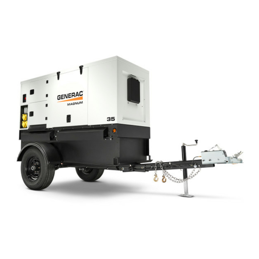
- Page 1 Owner’s Manual Diesel Generator MMG35DF4 • MMG45IF4 • MMG55DF4 Up to SN 3005615838 01306 For technical assistance contact: www.generacmobileproducts.com Technical Support 1-800-926-9768 SAVE THIS MANUAL FOR FUTURE REFERENCE...
- Page 2 Engine and generator serial numbers are located on separate Unit Serial No. data plates affixed to the engine and generator respectively. When contacting a Generac Mobile Authorized Service Dealer (GMASD) about parts and service, always supply the complete Engine Model No.
-
Page 3: Table Of Contents
Table of Contents Section 1: Introduction and Safety Low Idle Switch ............26 Wet Stacking ..............26 Introduction ..............1 Read This Manual Thoroughly ........1 Cold Weather Operation ..........27 How to Obtain Service ..........1 Using a Booster Battery or Charger (if equipped) ..28 Safety Rules ..............1 Generator Output Connections ........28 Safety Symbols and Meanings ........1... - Page 4 Engine Break-In Requirements—John Deere ..41 Resetting Maintenance Alarms ........ 41 Exhaust Filter Service Requirements ...... 41 Checking Generator Drive Plate Torque ....41 Jack Maintenance ............42 Side-Wind Models ............. 42 Top-Wind Models ............42 Trailer Wheel Bearings ..........42 Section 5: Troubleshooting General Troubleshooting ..........
-
Page 5: Section 1: Introduction And Safety
Section 1: Introduction and Safety Introduction Safety Rules Thank you for purchasing a Generac Mobile product. This The manufacturer cannot anticipate every possible unit has been designed to provide high performance, circumstance that might involve a hazard. The warnings in... -
Page 6: General Hazards
Introduction and Safety General Hazards WARNING DANGER Risk of injury. Do not operate or service this machine if not fully alert. Fatigue can impair the ability to Asphyxiation. Running engines produce carbon service this equipment and could result in death or monoxide, a colorless, odorless, poisonous serious injury. -
Page 7: Electrical Hazards
Introduction and Safety Electrical Hazards Lifting Hazards WARNING DANGER Personal injury. Failure to properly connect Electrocution. In the event of electrical accident, immediately shut power OFF. Use non-conductive lifting cables, chains, or straps could result in implements to free victim from live conductor. Apply death, serious injury, or property damage. -
Page 8: Fuel Hazards
Introduction and Safety Battery Hazards Fuel Hazards DANGER DANGER Explosion and fire. Fuel and vapors are extremely Electrocution. Do not wear jewelry while flammable and explosive. No leakage of fuel is working on this equipment. Doing so will permitted. Keep fire and spark away. Failure to do result in death or serious injury. -
Page 9: Operating Safety
Introduction and Safety Operating Safety Positioning the Unit WARNING Crushing hazard. Verify unit is properly secured and on level ground. An unsecured unit can suddenly roll or move, causing death or serious injury. (000234a) The area immediately surrounding the unit should •... -
Page 10: Safe Towing Techniques
However, NHTSA cannot become involved in an individual problem between you, your GMASD, or Generac Mobile. To contact NHTSA, you may either call the Auto Safety Hotline toll-free at 1-888-327-4236 (TTY:1-800-424-9153), go to http://www.safercar.gov;... -
Page 11: Safety And Operating Decals
Introduction and Safety Safety and Operating Decals This unit features numerous safety and operating decals. Replace any missing or hard-to-read decals and use care These decals provide important operating instructions and when washing or cleaning the unit. Decal part numbers warn of dangers and hazards. - Page 12 Introduction and Safety 008084 Figure 1-4. Exterior Decals Owner’s Manual for Mobile Generator...
- Page 13 Introduction and Safety Generator can automatically start which can cause serious injury. Disconnect battery before servicing. Der Generator kann automatisch anspringen und schwere Verletzungen verursachen. Vor der Instandsetzung die Batterieverbindungen lösen. El generador puede arrancar automáticamente, lo que puede causar graves lesiones.
- Page 14 Introduction and Safety STARTING THE GENERATOR DAS STARTEN DES GENERATORS / COMIENZO DEL GENERADOR / COMMENCEMENT DU GÉNÉRATEUR STOPPING THE GENERATOR DAS AUFHÖREN DES GENERATORS / PARADA DEL GENERADOR / ARRÊT DU GÉNÉRATEUR A0000639819 OPERATING INSTRUCTIONS BETRIEBSANLEITUNG Before starting Vor dem Starten 1.
-
Page 15: Section 2: General Information
Section 2: General Information Specifications Description Unit of Measure MMG35DF4 MMG45IF4 MMG55DF4 Engine ® ® John Deere John Deere Isuzu Make (Model) — (3029HFG03) (3029HFG03) (4LE2XAGV01) Rated Power Output hp (kW) 48 (36) 64 (48) 74 (55) Operating Speed 1,800... -
Page 16: Unit Dimensions
General Information Unit Dimensions 01906 Figure 2-1. Unit Dimensions—MMG35DF4, MMG45IF4, MMG55DF4 Skid Mounted 95 in (2.41 m) 39 in (0.99 m) 65 in (1.65 m) Trailer Mounted 152 in (3.81 m) 58 in (1.45 m) 83 in (2.11 m) Owner’s Manual for Mobile Generator... -
Page 17: Unit And Serial Number Locations
General Information Unit and Serial Number Locations Figure 2-2 to locate the unit ID tag (A) (located behind breaker door beneath breakers) and vehicle identification number (VIN) tag (B). Important information such as the unit model number, serial number, VIN, and tire loading information are listed on these tags. -
Page 18: Component Locations
General Information Component Locations Exterior 008881 Figure 2-3. Exterior Components Engine exhaust Breaker panel access door Radiator access panel Coolant and oil drain Unit lift point Lug box access door Fuel fill port Receptacle panel Side marker M Emergency stop switch Rear stabilizer mount Tail light (2 locations) Tie-down point... -
Page 19: Connection Panel
General Information Connection Panel 01882 Figure 2-4. Connection Panel Components Main circuit breaker Ground connection lug Panel light Connection lugs 50A circuit breaker (3 locations) Cam lock receptacle (5 locations) (if equipped) Service lights switch 120V/240V twist-lock outlets 20A circuit breaker (2 locations) M Connection for optional equipment Inlet Lug door safety switch 120 V GFCI outlet (2 locations) -
Page 20: Control Panel
General Information Control Panel 008882 Figure 2-5. Control Panel Components Genset controller Generator lights switch Panel light G Engine speed switch Voltage selector switch Controller power switch [not used] Voltage adjustment dial (Potentiometer) Fuel transfer switch Owner’s Manual for Mobile Generator... -
Page 21: Genset Controller
General Information Genset Controller Figure 2-6. The genset controller displays real-time The controller is programmable. It can automatically start operational data, monitors functions of the generator and and stop the genset according to schedule, fault engine, shuts down the unit for certain fault conditions, condition, or load demand. - Page 22 General Information (A) Navigation Buttons Emergency Stop indicator LED. Figure 2-7. Used to navigate the operator pages. Indicates Emergency Stop switch is active • (pushed in). Resolve by deactivating (pulling out) Emergency • Stop switch. Shutdown indicator LED. 010418 Indicates a shutdown alarm is present. •...
-
Page 23: Controller Modes
General Information NOTE: To modify the AUTO mode programmed schedule, (K) PAS valve test switch (if equipped) use the Deep Sea Configuration Suite software. When PAS test is active, the PAS is cycled to verify function. STOP/RESET Mode STOP/RESET mode is distinguished by the following: (L) MANUAL Mode LED When illuminated, MANUAL mode is active. - Page 24 General Information The Generator page displays the following generator The ECU Current DTC page displays active ECU DTCs. data, in real time (press ▲ or ▼ to scroll). Press ► to view previous ECU DTCs. NOTE: See engine manual for information on ECU DTCs. Voltage (ph-N) •...
-
Page 25: Maintenance Alarms
General Information Serial Port Page About Page The Serial Port page displays information about the RS232 serial port, which enables data transfers. If an external modem is connected to the serial port, modem information also displays. NOTE: The Serial Port page display may vary, in accordance with controller configuration. -
Page 26: Selective Catalytic Reduction (Scr) Monitoring
General Information Selective Catalytic Reduction (SCR) Monitoring This unit is equipped with a selective catalytic reduction SCR Inhib: This area displays the disabled • (SCR) system to meet Tier 4 EPA emissions standards. regeneration indicator above the words SCR INHIB This section gives an explanation of the indicators that - SOLID when auto exhaust filter cleaning is are displayed on the SCR status page of the engine tab. -
Page 27: Voltage Selector Switch
General Information Voltage Selector Switch WARNING Electric Shock. Never change the voltage selector switch while the engine is running or the controller is on. Doing so could result in death, serious injury or equipment damage. (000302) The voltage selector mechanically configures the generator main windings. - Page 28 General Information This page intentionally left blank. Owner’s Manual for Mobile Generator...
-
Page 29: Section 3: Operation
Section 3: Operation Pre-start Checklist Verify all electrical connections at the connection lugs, if equipped, are tight and wired correctly. All items in the pre-start checklist must be completed Verify the voltage selector switch is set to the desired before starting the unit. -
Page 30: Auto (Remote) Starting The Unit
Operation to cool. Pressing the ENTER () button will clear 4. Remove the jumper wire from the remote start the alarm and reset the controller. terminal block and the engine runs the stop sequence. Reconnect any necessary wires from NOTE: Engine preheat is controlled by the ECU. the remote start switch (transfer switch) to the 4. -
Page 31: Cold Weather Operation
Operation of its full load capacity, causing unburned fuel to accumulate in the exhaust system. Wet stacking can be detected by continuous black exhaust when the unit is under a constant load. It can also cause fouling of injectors and buildup on engine valves. Diesel engines operate properly when applied loads are between 30% and 100% capacity. -
Page 32: Using A Booster Battery Or Charger (If Equipped)
Operation 4. Connect one end of the other jumper cable to the Using a Booster Battery or NEGATIVE (-) post of the booster battery. Charger (if equipped) 5. Complete hookup making last connection of the NEGATIVE (-) cable to a good WARNING ground on the engine frame and away from the Explosion. -
Page 33: Generator Cam Lock Connections (If Equipped)
Operation The connection lug door is equipped with safety interlock Figure 3-5. The unit may be equipped with cam lock switches that will trip the main circuit breaker and disable connections (A) located below the receptacles. These the voltage regulator if the door is opened while the unit receptacles provide connection points to attach external is operating. -
Page 34: Fine Voltage Adjustment
The receptacles is 139 volts and the voltage at the three twist- operator may also be required to perform a manual lock receptacles is 240/139 volts. Generac Mobile does regeneration. not recommend using the receptacles in the 480V NOTE: Always park the unit in a safe location for position. -
Page 35: Disabling Automatic (Auto) Exhaust After-Treatment Cleaning (If Equipped)
Operation extended period of time (approximately 45 minutes). 3. Enter the SCR status screen and verify the re- Cleaning is complete when the regeneration indicator generation indicator appears above the words SCR remains off. LAMP SOLID. Selective Catalytic Reduction (SCR) Monitoring. -
Page 36: Alternative Load Device (Ald) (If Equipped)
Operation Note: When using transfer switch in AUTO mode, the Accessing the Configuration Menu Engine Speed switch must be in the RUN position. 1. With the unit stopped, press ▲, ►, ▼, or ◄ to navigate to the maintenance screens from any of the operator screens. -
Page 37: Setting Up A Daily Scheduled Run
Operation Emergency Stop Switch Monday-Sunday Week (of month) First, Second, Third, Fourth CAUTION Equipment Damage. The emergency stop switch is NOTE: If setting up a daily scheduled run, select Weekly not to be used to power down the unit under normal Run Mode, then set start time and duration for each day operating circumstances. -
Page 38: Towing The Unit
Operation Towing the Unit WARNING Personal injury. Trailer must be securely coupled to the hitch with the chains correctly attached. Uncoupled or unchained towing could result in death or serious injury. (000233a) WARNING Personal injury. Do not operate unit during transport. 007620 Doing so could result in death, serious injury, or property damage. - Page 39 Operation 3. See Figure 3-8. Attach slings, chains, or hooks to the central lift point (A). ###### 01306 Figure 3-8. Central Lift Point Tying Down the Unit When securing the unit for transportation, verify the equipment being used to fasten the unit is in good condition and has sufficient strength to hold the unit in place during transport.
- Page 40 Operation This page intentionally left blank. Owner’s Manual for Mobile Generator...
-
Page 41: Section 4: Maintenance
• LLC recommends that all maintenance work be per- Verify the circuit breakers are turned OFF (O). • formed by a Generac Mobile Authorized Service Dealer Activate (push in) the emergency stop switch. • (GMASD). Regular maintenance, replacement, or repair Disconnect the negative (-) terminal on the battery. -
Page 42: Engine Oil Recommendations
Maintenance – DO NOT start the unit if the engine oil level is below the add mark on the dipstick. – Normal operating level is in the cross-hatch pattern between the FULL and ADD markings on the dipstick. – Add oil only if the oil level is below the ADD mark on the bottom of the cross-hatch pattern on the dipstick. -
Page 43: Basic Maintenance Schedule
Maintenance Basic Maintenance Schedule See the relevant OEM engine manual for a complete list Maintenance records may be required to complete a of maintenance requirements. Failure to comply with the warranty request. procedures as described in the engine manual will nullify IMPORTANT NOTE: Refer to the engine operator’s warranty, decrease... - Page 44 Maintenance Basic Maintenance Schedule—John Deere Engine First 100 Every 250 Every 500 Every Every Item Daily Hr (Break- 2,000 Hr 6,000 Hr Required in Period) Check engine oil level Check engine coolant level Check fuel level Check tire pressure ...
-
Page 45: Engine Break-In Requirements-Isuzu
Maintenance 4. Press to move the cursor (blue highlighted text) Engine Break-In Requirements— down to the maintenance group. Isuzu 5. Press ► to access the sections. Press to NOTE: The EPA final Tier 4 Isuzu engines have an highlight the maintenance section. -
Page 46: Jack Maintenance
Maintenance 3. Tighten each drive plate bolt as shown below:. Grease Unit Torque: ft-lb (Nm) MMG35DF4 40 (54) MMG45IF4 30 (40) MMG55DF4 40 (54) 4. Install generator fan guard. 5. Connect battery. 002824a Jack Maintenance The following procedures should be performed annually. -
Page 47: Section 5: Troubleshooting
Section 5: Troubleshooting General Troubleshooting This information is intended to be a check or verification manual for additional troubleshooting information. Proce- for simple causes that can be located and fixed. It does dures that require in-depth knowledge or skills should be not cover all types of problems. - Page 48 Troubleshooting This page intentionally left blank. Owner’s Manual for Mobile Generator...
-
Page 49: Section 6: Wiring Diagrams
Section 6: Wiring Diagrams 3-Position AC Box 90580_ORG_10.14.14 Owner’s Manual for Mobile Generator... -
Page 50: 3-Position Ac Box
Wiring Diagrams 3-Position AC Box 90632_ORG_01.14.15 Owner’s Manual for Mobile Generator... -
Page 51: 4-Position Ac Box
Wiring Diagrams 4-Position AC Box 90581_ORG_10.14.14 Owner’s Manual for Mobile Generator... -
Page 52: 4-Position Ac Box
Wiring Diagrams 4-Position AC Box 90633_ORG_01.20.15 Owner’s Manual for Mobile Generator... -
Page 53: Receptacles
Wiring Diagrams Receptacles 3 POS BLK GND STUD BRKR BRKR BRKR 20 20 GFCI1 GFCI2 2 POS BLK GN/YL GN/YL GN/YL 90582_ORG_08.18.14 Engine Heater BLOCK HEATER WHITE WHITE SPLICE WHITE 28407 66080 RECEPTACLE 68635 50125 GREEN GREEN TERMINAL 65006 SPLICE BLACK BLACK BLACK... -
Page 54: Wiring Buck (If Equipped)
Wiring Diagrams Wiring Buck (If Equipped) TO 120V TO 120V BREAKERS BREAKERS VOLTAGE RELAY VOLTAGE RELAY POWER POWER RELAY RELAY 3 POS BLK 3 POS BLK BUCK BUCK XFMR XFMR 90583_ORG_08.18.14 Power Zone PMG 1 2 3 4 5 6 7 REMOVE JUMPERS FOR PMG 90589_ORG_08.18.14 Owner’s Manual for Mobile Generator... -
Page 55: Control Box
Wiring Diagrams Control Box LEGEND - ALTERNATOR GROUND STUD - CURRENT TRANSFORMER - POSITIVE AIR SHUTDOWN - ANALOG VOLTAGE REGULATOR - ENGINE CONTROL UNIT PH SW - PHASE SWITCH CONN1 - ENGINE CONNECTOR GENTB - GENERATOR TERMINAL BLOCK - PERMANENT MAGNET GENERATOR - TERMINAL BLOCK CONN2 - D/C CONNECTOR... -
Page 56: Trailer Lights
Wiring Diagrams Trailer Lights TRAILER PLUG RIGHT AMBER MARKER LAMP LEFT AMBER MARKER LAMP RIGHT LEFT MARKER MARKER LAMP LAMP STOP-TURN SIGNAL STOP-TURN LAMP SIGNAL (RIGHT) LAMP (LEFT) LICENSE PLATE LAMP 90584_ORG_10.02.14 Owner’s Manual for Mobile Generator... -
Page 57: Trailer Brakes
Wiring Diagrams Trailer Brakes SPLICE SPLICE SPLICE SPLICE SPLICE SPLICE SPLICE SPLICE SPLICE SPLICE SPLICE SPLICE SPLICE SPLICE 90286_E_03.18.14 Owner’s Manual for Mobile Generator... -
Page 58: 12-Volt Battery Charger
Wiring Diagrams 12-Volt Battery Charger WHITE RECEPTACLE BATTERY 65285 66212 CHARGER GREEN 66212 BLACK BREAKER 15568 TERMINALS 65003 12 V BATTERY 90593_B_09.19.16 Power Zone Low Oil Level (If Equipped) LEVEL 90595_ORG_10.31.14 Owner’s Manual for Mobile Generator... - Page 60 ©2020 Generac Mobile Products, LLC All rights reserved. Generac Mobile Products, LLC Specifications are subject to change without notice. 215 Power Drive, Berlin, WI 54923 No reproduction allowed in any form without prior written GeneracMobileProducts.com │800-926-9768 │920-361-4442 consent from Generac Mobile Products, LLC.
Need help?
Do you have a question about the MMG35DF4 and is the answer not in the manual?
Questions and answers