
Related Manuals for Generac Mobile MDE330P


Summary of Contents for Generac Mobile MDE330P
- Page 1 Owner’s Manual Diesel Generator MDE330P For technical assistance contact: www.generacmobileproducts.com Technical Support 1-800-926-9768 SAVE THIS MANUAL FOR FUTURE REFERENCE...
- Page 2 Unit Serial No. Engine and generator serial numbers are located on separate data plates affixed to the engine and generator. When contacting a Generac Mobile Authorized Service Engine Model No. Dealer (GMASD) about parts and service, supply the complete model number and serial number of the unit.
-
Page 3: Table Of Contents
Table of Contents Section 1: Introduction and Safety Fuel System ............23 Fuel Tank ..............23 Introduction ............1 Dual Diesel Exhaust Fluid (DEF) Tank System ..23 Read This Manual Thoroughly ........1 3-Way Fuel Valve (If Equipped) ........23 How to Obtain Service ..........1 Engine Aftertreatment Monitoring ...... - Page 4 Jack Maintenance ..........54 Hitch and Coupling Guidelines ........40 Preparing Unit for Towing ......... 40 Side-Wind Models ............. 54 Recommended Towing Speed ........41 Top-Wind Models ............55 Lifting the Unit ...........41 Trailer Wheel Bearings ........55 Trailer and Skid-Mounted Units ........ 41 Skid-Mounted Units ONLY ........
-
Page 5: Section 1: Introduction And Safety
Section 1: Introduction and Safety Introduction Safety Rules Thank you for purchasing a Generac Mobile product. The manufacturer cannot anticipate every possible cir- This unit has been designed to provide high perfor- cumstance that might involve a hazard. The warnings in... -
Page 6: General Hazards
General Hazards WARNING Risk of injury. Do not operate or service this machine DANGER if not fully alert. Fatigue can impair the ability to Asphyxiation. Running engines produce carbon operate or service this equipment and could result in monoxide, a colorless, odorless, poisonous death or serious injury. -
Page 7: Electrical Hazards
Electrical Hazards Lifting Hazards DANGER WARNING Electrocution. In the event of electrical accident, Personal injury. Failure to properly connect immediately shut power OFF. Use non-conductive lifting cables, chains, or straps could result in implements to free victim from live conductor. Apply death, serious injury, or property damage. -
Page 8: Battery Hazards
• Battery Hazards DO NOT fill fuel tank near an open flame, while smoking, or while engine is running. DO NOT fill tank in an enclosed area with poor ventilation. DANGER • DO NOT operate with the fuel tank cap loose or Electrocution. -
Page 9: Starting The Unit
Starting the Unit DANGER Electrocution. DO NOT use the unit if electrical cord is cut or worn through. Doing so will result in death or serious injury. (000263a) • DO NOT start a unit in need of repair. Towing Safety Towing a trailer requires care. - Page 10 DANGER GEFAHR PELIGRO DANGER BREATHING DIESEL ENGINE EXHAUST EXPOSES YOU TO CHEMICALS KNOWN TO THE STATE OF CALIFORNIA TO CAUSE CANCER AND BIRTH DEFECTS OR OTHER REPRODUCTIVE HARM. 1). ALWAYS START AND OPERATE THE ENGINE IN A WELL-VENTILATED AREA. 2). IF IN AN ENCLOSED AREA, VENT THE EXHAUST TO THE OUTSIDE. 3).
- Page 11 Operator’s manual must be stored on machine. Replacement operator’s manual can be ordered through your local Generac distributor. Das Benutzerhandbuch muss an der Maschine aufbewahrt werden. Zur Bestellung von Ersatzhandbüchern wenden Sie sich bitte an Ihren Generac-Händler. El manual del operador debe guardarse en la máquina. Puede solicitar un manual del operador de reemplazo a través de su distribuidor local de Generac.
- Page 12 Operator’s manual must be stored on machine. Replacement operator’s manual can be ordered through your local Generac distributor. Das Benutzerhandbuch muss an der Maschine aufbewahrt werden. Zur Bestellung von Ersatzhandbüchern wenden Sie sich bitte an Ihren Generac-Händler. El manual del operador debe guardarse en la máquina. Puede solicitar un manual del operador de reemplazo a través de su distribuidor local de Generac.
-
Page 13: Section 2: General Information
Section 2: General Information Specifications Description Unit Of Measure MDE330P Engine Make (Model) — ® Perkins (1706J-E93TAG2) Rated Power Output—Prime hp (kW) 411 (307) Operating Speed 1,800 Fuel Consumption—100% Prime gph (L/hr) 19.7 (74.6) Fuel Consumption—75% Prime gph (L/hr) 14.5 (54.9) Fuel Consumption—50% Prime... - Page 14 Description Unit Of Measure MDE330P 480/277 VAC kW/kVA (A) 290/363 (437) 600/346 VAC kW/kVA (A) 290/363 (349) 3Ø Prime: 208/120 VAC kW/kVA (A) 264/330 (917) 240/139 VAC kW/kVA (A) 264/330 (795) 480/277 VAC kW/kVA (A) 264/330 (397) 600/346 VAC kW/kVA (A)
-
Page 15: Unit Dimensions
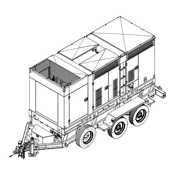
Unit Dimensions 013481 Figure 2-1. Unit Dimensions Skid Mounted 168.0 in (4.26 m) 64.0 in (1.62 m) 101.0 in (2.56 m) Trailer Mounted 232.0 in (5.89 m) 94.5 in (2.4 m) 115.0 in (2.92 m) Owner’s Manual for Mobile Generator... -
Page 16: Unit Id And Vin Tag Locations
Unit ID and VIN Tag Locations mended to run the engine in idle (1100 RPM) conditions for more than 10 minutes. This prevents the engine con- The unit ID tag is located on the control Figure 2-2 troller from activating the load management system and panel face. -
Page 17: Component Locations-Unit Exterior
Component Locations—Unit Exterior 015077 Figure 2-3. Exterior Components Hot air/exhaust duct Coolant drain Central lift point Engine oil drain Diesel exhaust fluid (DEF) fill port Generator and link board access door Fuel fill 3-phase AC power distribution access door DEF drain (not shown—unit underside) Breaker panel access panel Ladder Stabilizer jack (2 locations) (if equipped) -
Page 18: Component Locations-Unit Interior
Component Locations—Unit Interior 015078 Figure 2-4. Interior Components Diesel oxidation catalyst (DOC) and Diesel particulate Engine charge alternator (behind engine fan) filter (DPF) Selective catalytic reduction (SCR) module Radiator/charged air cooler Air filter Radiator fill Generator box Engine oil filters Battery charger (if equipped) Link board panel DEF tanks... -
Page 19: Component Locations-Ac Distribution Panel
Component Locations—AC Distribution Panel 015079 Figure 2-5. AC Distribution Panel Components Main Line Circuit Breaker (MLCB) Cam lock receptacle (10 locations) (if equipped) Charging lever Lug door safety switch Neutral bonding bar Parallel ports Ground terminal Emergency stop switch Terminal lug (4 locations) Owner’s Manual for Mobile Generator... -
Page 20: Component Locations-Receptacle Panel
Component Locations—Receptacle Panel 014007 Figure 2-6. Receptacle Panel Components 125 V, 15 A battery charger shore power plug (NEMA 5- 120 V, 20 A, GFCI, duplex outlets (NEMA 5-20R) 15P) (If equipped) Receptacle panel circuit breakers 125 V, 30 A, winter heater shore power plug (NEMA L5- 30P) (If equipped) 240 V, 50 A, 3 pole, twist-lock outlet (CS6369) Owner’s Manual for Mobile Generator... -
Page 21: Component Locations-Control Panel
Component Locations—Control Panel 014008 Figure 2-7. Control Panel Components Panel light Genset controller RUN-IDLE switch Hour meter Switch for control panel lights and optional interior lights Owner’s Manual for Mobile Generator... -
Page 22: Genset Controller
RS232 serial port (not shown—controller backside) • Genset Controller With Paralleling (If To verify the units intended for paralleling are appropriate for the load, contact Generac Mobile at Equipped) 1-800-926-9768. If the unit is equipped to run in parallel with other units, for unit paralleling setup and operation. - Page 23 (A) Navigation Buttons (3) Emergency Stop indicator LED. • Figure 2-9. Used to navigate the operator pages. Indicates Emergency Stop switch is active (pushed in). • Resolve by deactivating (pulling out) Emergency Stop switch. (4) Shutdown indicator LED. • Indicates a shutdown alarm is present. •...
-
Page 24: Controller Modes
(K) PAS valve test switch (if equipped) AUTO mode utilizes the remote start connections. For remote starting procedures, see Operation. When PAS test is active, the PAS is cycled once for 15 seconds to verify function. Press and hold test button AUTO mode utilizes a programmed schedule, which can until message is displayed on screen. - Page 25 NOTE: The list in the previous column varies according to generator make, model, and features. NOTE: As possible, distribute electrical loads equally among generator lines. Minor load imbalances (10% or less) usually do not cause problems. When loading gen- erator, observe the load (amperage) on each line. 014030 Alarms Page Figure 2-11.
-
Page 26: Maintenance Alarms
• About Page Newest event displays at top of log; oldest at bottom. Serial Port Page The Serial Port page displays information about the RS232 serial port, which enables data transfers. If an external modem is connected to the serial port, modem information also displays. -
Page 27: Fuel System
Fuel System Standard units are equipped with the following fuel sys- tem components: • Single wall fuel tank • Engine fluid containment • Engine fluid containment sensor Fuel Tank for fuel tank components. Figure 2-21 015091 Figure 2-22. Dual DEF Tank System Fill neck Primary tank Secondary tank... -
Page 28: Engine Aftertreatment Monitoring
to the engine manufacturer for more information about this. Engine Aftertreatment Monitoring This section describes the indicators that display on the After Treatment Status page of the Engine tab. Figure 2-24. This unit is equipped with a diesel oxidation catalyst (DOC), diesel particulate filter (DPF), and selec- tive catalyst reduction system (SCR), to meet Tier 4 Final EPA emissions standards. -
Page 29: Alternator
Icon Fault Description ECU Amber Alarm The module received an Amber fault condition from the engine ECU.. ECU Red Alarm The module received a Red fault condition from the engine ECU. DPF Active The module received a fault indication from the engine ECU informing that the Diesel Particulate Filter is active. -
Page 30: Cold Weather Starting Aids And Operation (If Equipped)
Cold Weather Starting Aids and Oper- (D) Fuel Filter Heaters (×2) ation (If Equipped) 50 W, 24 VDC. Component Locations (E) Oil Pan Heater 2-26. This unit may be equipped with one or Figure 1,000 W, 120 VAC. Requires optional shore power inlet more starting aids... - Page 31 (A) From 32 to 0 °F (0 to -18 °C) Standard Cold Weather Package is recommended. (B) From 32 to -40 °F (0 to -40 °C) Extreme Cold Weather Package is recommended. NOTE: See for components in each package. Table 2-1. Table 2-1.
- Page 32 This page intentionally left blank. Owner’s Manual for Mobile Generator...
-
Page 33: Section 3: Operation
Section 3: Operation Overview • Check engine fan belt guard. • Check engine exhaust system for loose or rusted The engine can be started in low-idle or at normal operat- components. ing speed (1,800 rpm). In cold weather, it is recom- mended to start the engine in low-idle condition, and idle •... -
Page 34: Using An External Battery Charger
and oil. Preheat time is reduced to 2 hours if ambient temperatures have not been colder than -4F (-20C). These heaters will cycle on and off as needed during preheat cycle. When engine has started, the inlet receptacle can be disconnected as heater will no longer be needed if engine continues to run. -
Page 35: Lockout Function
3. Loosen nuts securing link board plate to panel. and/or fault codes due to high fuel pressure restrictions. 4. Position link board according to the correct config- A lift pump can be installed to push fuel from an external uration, to obtain the desired output voltage. tank if a longer supply hose is required to connect the 5. -
Page 36: Manually Starting The Unit
1. Switch the battery disconnect switch to the ON position. 015113 015080 Figure 3-4. Battery Disconnect Switch Figure 3-3. 3-Way Fuel Valve NOTE: See Figure 3-5. The Home page displays when Main Tank Supply the controller is ON, and no other page has been Aux Tank Supply selected. -
Page 37: Auto (Remote) Starting The Unit
5. If the engine does not start and run after three Use AUTO (remote start) mode to start from somewhere crank cycles, the controller displays the fail to start other than the control panel by using a transfer switch. alarm. The starting sequence can be repeated after AUTO mode is the normal setting when the unit is being the starter has had a minimum of two minutes to used as a standby power source. -
Page 38: Parallel Setup And Operation (If Equipped)
Parallel Setup and Operation (If Equipped) This system is designed to work with generators that are connected on the mobile switching center (MSC) network only and not with the utility or any other independent power source. All other power sources must be isolated from the MSC network to prevent potential damage due to power sources closing out of phase. -
Page 39: Switching Controller Mode
IMPORTANT NOTE: This procedure is only permit- 2. Secure all electrical connections to each unit and a common bus. Before connecting, ensure all wiring ted on non-parallel capable machines. Machines set is properly color coded or labeled. up with parallel controls will not respond to voltage adjustments when the breaker is closed. -
Page 40: Motorized Breaker (If Equipped)
Connection Lugs DANGER Electrical backfeed. Use only approved switchgear to isolate generator from the normal power source. Failure to do so will result in death, serious injury, and equipment damage. (000237) DANGER Electrocution. Do not disable or modify the 014017 connection box door safety switch. -
Page 41: Connecting To Lugs
Connecting to Lugs WARNING Connect to the lugs by routing power cables through the Electric Shock. Verify all connections to the opening in the bottom of the door. The tightening torque cam lock receptacles are made to one side for the set screws on the connection lug is 30 ft-lb (41 only. -
Page 42: Convenience Receptacles
NOTE: Generac Mobile does not recommend using the receptacles in the 600 V position. •... -
Page 43: Transfer Switch
down voltage to an acceptable range. Generac fer switch automatically returns the load back to the nor- Mobile does not recommend using the receptacles mal source when power is restored back to operating in the 600 V position. levels. Transfer Switch DANGER Loss of life. -
Page 44: Emergency Stop Switch
5. After the unit shuts down, wait for the battery dis- emergency situations and not be used to shutdown the connect LED to turn off. When the LED shuts off, it generator during normal operation. Using the emergency is safe to switch the disconnect switch to off. stop switch overrides normal shutdown sequence. -
Page 45: Recommended Towing Speed
First pass tighten to 50–60 ft-lb (67–81 Nm). Second pass tighten to 150–200 ft-lb (203–271 Nm). Third pass tighten to 275–325 ft-lb (373–441 Nm). 001441 Figure 3-18. Lug Sequence Detail (B) WARNING 015082 Property or Equipment Damage. Tighten wheel lug Figure 3-19. -
Page 46: Dragging The Unit (Skid Mounted Units Only)
2. Attach the chains to a suitable tow vehicle (B). NOTE: The D-Rings are not to be used for lift the entire generator. D-Rings are designed for dragging generator on skid frame. Tying Down the Unit When securing the unit for transportation, verify the equipment being used to fasten the unit is in good condi- tion and has sufficient strength to hold the unit in place during transport. -
Page 47: Section 4: Maintenance
Section 4: Maintenance Emissions Information bar reaches the red section on the gauge (20 in. H2O). For emissions information, see the OEM diesel engine • Inspect condition of electrical cords. DO NOT use manual. the unit if insulation is cut or worn through. •... -
Page 48: Fuel Recommendations
• machine. The fuel tank level can be monitored on the Inspect coolant level. Coolant should be visible in control panel display or the analog gauge located on top the sight-glass, located on the top tank of the of the fuel tank near the battery tray on roadside of the radiator. -
Page 49: Aftermarket Oil Additives
API CK-4 and ACEA E9 oil categories have the following of the engine oil. Use oil analysis also to determine the oil chemical limits: change interval that is optimum. • 0.1% maximum sulfated ash IMPORTANT NOTE: DO NOT use API FA-4 oil in •... -
Page 50: Oil Analysis
To achieve the best performance from a Perkins engine, the oil according to the specification during the conform to the following guidelines: entire oil change interval. • to find the correct oil viscosity Figure 4-1 Coolant Recommendation grade for your engine. •... -
Page 51: Def Recommendations
DEF Recommendations serves as a drain for the tanks in the event it needs to be drained due to contamination. This line is wrapped with insulation and an embedded heater to prevent the DEF in CAUTION the line from freezing. This heater will be turned on auto- Equipment damage. -
Page 52: Basic Maintenance Schedule
• Basic Maintenance Schedule 316L (S31603) Alloys and metals: See the original equipment manufacturer’s operating • manual for a complete list of maintenance requirements. Chromium Nickel (CrNi) Failure to comply with the procedures as described in the • Chromium Nickel Molybdenum (CrNiMo) OEM engine manual will nullify the warranty, decrease •... - Page 53 Table 4-5. Basic Maintenance Schedule Every 200,000 Every Every Every Every Every Initial Every Every Every Every Every Every Every (760,00 12,000 Item Daily 500 Hr/3 500 Hr/1 10,000 250 Hr 500 Hr 500 Hr 2,000 Hr 2,500 Hr 3,000 Hr 4,000 Hr 5,000 Hr 6,000 Hr...
-
Page 54: Resetting Maintenance Alarms
Table 4-5. Basic Maintenance Schedule Every 200,000 Every Every Every Every Every Initial Every Every Every Every Every Every Every (760,00 12,000 Item Daily 500 Hr/3 500 Hr/1 10,000 250 Hr 500 Hr 500 Hr 2,000 Hr 2,500 Hr 3,000 Hr 4,000 Hr 5,000 Hr 6,000 Hr... -
Page 55: Def Tank Cleaning
DEF Tank Cleaning The correct DEF concentration is 32.5% urea. If the DEF concentration is not within specification, drain the DEF Proceed as follows to clean the DEF tank: tank, flush with distilled water, and fill with new or good DEF. -
Page 56: Def Storage Guidelines
DOC, SCR, and DPF Cleaning Opera- water, and fill with new or good DEF, contact a GMASD, to determine how to clean and purge the system. tions If water has been added to the DEF tank, a tank cleaning is necessary. After refilling the tank, check the DEF con- WARNING centration. -
Page 57: Regeneration Triggers
The regeneration active indicator will be illuminated when regeneration is being performed. Interruptions of the regeneration are acceptable. NOTE: Automatic adjustments of engine speed may be noticed during regenerations. If regeneration is taking Figure 4-4. DPF Indicator and STOP Lamp place and the engine is taken to low idle, the engine 10 minutes after the illumination of the DPF indicator and speed may remain elevated to maintain the regeneration. -
Page 58: Checking Generator Drive Plate Torque
Table 4-6. Regeneration Triggers Reason For Duration Type Strategy Regen Interval Trigger (Minutes) Primary Triggers Upon cold startup (coolant temp. On cold startup. (LSR & HSR) maintenance below 104 °F (40 °C), the A/T will be maintained. Frequency depends on how often application starts up Coolant temp. -
Page 59: Top-Wind Models
Top-Wind Models remove the hub from the spindle. A new oil seal must be installed before reassembly or the old seal will leak upon • Apply a light weight oil to the screw stem. re-installation and use. When re-installing a new oil seal, be sure to correctly orient the seal. - Page 60 This page intentionally left blank. Owner’s Manual for Mobile Generator...
-
Page 61: Section 5: Troubleshooting
Section 5: Troubleshooting General Troubleshooting This information is intended to be a check or verification for simple causes that can be located and fixed. It does not cover all types of problems. See the OEM engine manual for additional troubleshooting information. Proce- dures that require in-depth knowledge or skills should be performed by a GMASD. - Page 62 This page intentionally left blank. Owner’s Manual for Mobile Generator...
-
Page 63: Section 6: Wiring Diagrams
Section 6: Wiring Diagrams GROUP G DIAGRAM LEGEND - AUX FUEL SWITCH (NOT USED ON MDE330) DSW1 - CUSTOMER LUG DOOR SAFETY SWITCH - CONTROL PANEL LIGHT - DC CHARGE ALTERNATOR DSW2 - LINK BOARD DOOR SAFETY SWITCH - POWER RELAY - LSA GENERATOR TERMINAL BLOCK - EMERGENCY STOP SWITCH - POWER ZONE POWER CONNECTOR... - Page 64 GROUP G DIAGRAM COMPONENTS LOCATED IN CIRCUIT BREAKER BOX NOTE: ALL WIRES ON THIS PAGE ARE 600V RATED WIRING FOR MANUAL & MOTORIZED MLCB TO LINK BOARD AØ BØ CØ CBC-1 CBC-4 220C VSC-1 CBC-2 CBC-5 VSC-2 CBC-3 CBC-6 VSC-3 JUMPER AØ...
- Page 65 GROUP G DIAGRAM RECEPTACLE PANEL (CONFIGURATION #1) XFMR1 TB3-L0 BUCK XFORMER TB3-T7 TERM FUNCTION NOTE: BUCK TRANSFORMER RELAY VOLTAGE SWITCHOVER COIL POINT AT ~137VAC MEASURED AT COIL. N.O. N.C. N.O. N.C. TB3-L0 6 (N.O.-B) 8 (N.C.-B) 2 (COIL) 4 (COM-B) CB2-1 7 (N.C.-A) CB1-1...
- Page 66 GROUP G DIAGRAM RECEPTACLE PANEL (CONFIGURATION #1) 240R-3 240R-2 240R-1 CS6369, STYLE B CS6369, STYLE B CS6369, STYLE B OUTPUT OUTPUT LOAD LOAD GFCI1 GFCI2 TB3-L0 TB3-L0 INPUT INPUT LINE LINE CB1-2 920A CB2-2 921A TB-GB TB-GB NEMA 5-20 NEMA 5-20 PAGE 4 OF 16 WIRING - DIAGRAM REVISION: B...
- Page 67 GROUP G DIAGRAM OPTIONAL HEATER SHORE POWER RECEPTACLE (NEMA L5-30) (LOCATED RIGHT SIDE OF ENGINE BAY ON CROSSMEMBER) MOUNTING BOLT ON BOX PHILLIPS&TEMRO 1000W 120V (LOCATED ON RECEPTACLE BOX) NON-WIRE INSERTION VIEW @300F @270F 2250W 120V ZEROSTART THERMOSTAT SETPOINT @100 F OPTIONAL BATTERY CHARGER SHORE POWER RECEPTACLE - (NEMA 5-15) (LOCATED BACKSIDE OF CONTROL BOX) PRONAUTIC 24-30P...
- Page 68 GROUP G DIAGRAM COMPONENTS LOCATED IN CONTROL PANEL DEEP SEA A109 AVR DEEP SEA A109 AVR CONNECTOR A CONNECTOR B PIN WIRE FROM PIN WIRE FROM PIN WIRE FROM AVRC-1 743A DS3-26 H L SCR AVRC-2 744A DS3-27 AVRC-3 AVRC-5 AVRC-4 AVRC-10 AVRC-9...
- Page 69 GROUP G DIAGRAM COMPONENTS LOCATED IN CONTROL PANEL NOTE: ALL WIRES ON THIS PAGE ARE 600V RATED MLCB A-7 DS4-43 MLCB B-12 DS1-13 MLCB B-15 220C 220C TB5-10X MLCB B-10 DS4-41 MLCB B-20 DS7-67 SPLICE 9 TB5-2Y EXTERNAL INTERNAL 10 11 CT3-2 398C CT2-2...
- Page 70 GROUP G DIAGRAM COMPONENTS LOCATED IN CONTROL PANEL PWR-1 PANEL GND LIS-5 CBC-1 AFS-5 HM-1 DS1-1 PL-WHT AVRC-8 CTC-1 DS2-15 PZC-5 575R TB11-1Y CTC-11 PZC-29 DS1-4 PZC-2 CTC-2 DS1-3 FB5-Y 220D DS1-2 220D CTC-10 220D FB4-Y 220C 220C DS4-40 CBC-4 220C 220C DS4-42...
- Page 71 GROUP G DIAGRAM COMPONENTS LOCATED ON CONTROL PANEL INNER DOOR 52 53 54 55 56 57 58 59 60 61 62 63 64 65 66 67 68 69 70 GEN VOLT SENSE BUS VOLT SENSE GEN CURRENT DIGITAL INPUTS (USE 55 AS COM ONLY WHEN USING 4TH CT,) (OTHERWISE USE 56 AS COM) DEEP SEA 8610 mkII CONTROLLER...
- Page 72 GROUP G DIAGRAM COMPONENTS LOCATED AT BACK OF CONTROL PANEL BOX WIRE FROM WIRE FROM WIRE FROM CRANK DS1-5 TB5-7X FB-D5 RUN SIGNAL (ACTIVE HI) FUEL LEVEL, 2WIRE 575S DS2-18 FLS-1 575R TB5-6X FLS-2 FUEL LEVEL, 2WIRE FUEL CONTAINMENT DS7-61 RBS-1 LOW CLNT LVL DS7-70...
- Page 73 GROUP G DIAGRAM COMPONENTS LOCATED IN ENGINE BAY FB-A2 220B 220B C60-10 220B C61-5 FB-B1 220B 220B WLS-A TCR-11 743A TCR-12 744A 743A PZC-43 CVH-1 PZC-28 TCR-10 SHLD 744A PZC-44 FFH-1 H1-1 C60-31 743A SHLD PZC-45 C60-32 744A FB-B2 GND1 FB-B5 RBS-2 FB-B6...
- Page 74 GROUP G DIAGRAM COMPONENTS LOCATED IN ENGINE BAY FB-A7 220H SMS-1 PZC-1 SPLICE 25 NOTE: 3A, 600V DIODE LINE OF DIODE (CATHODE) MUST BE ORIENTATED THE SAME AS IN THE DRAWING. BCH+ TCR-1 BATTERY BATTERY TO ENGINE BLOCK GENERATOR BCH- TCR-2 TO BACK OF LUG...
- Page 75 GROUP G DIAGRAM COMPONENTS LOCATED IN ENGINE BAY PIN LIST PIN LIST PIN LIST PIN LIST WIRE WIRE WIRE WIRE 220J 220B PLUG C60-1 SPLICE 4 C61-8 220B PLUG 220G SPLICE 4 SPLICE 24 C61-7 220P C60-15 PLUG PLUG PLUG 220Q C60-33 PLUG...
- Page 76 GROUP G DIAGRAM COMPONENTS LOCATED ON ENGINE/RADIATOR COMPONENTS LOCATED NEAR DUAL DEF TANKS PLUGS INTO SMS ON STARTER SPLICE 1B PZC-7 SPLICE 4 220B SPLICE 1A NEAR TOP OF RADIATOR COMPONENTS LOCATED ON FUEL TANK PZC-50 623A 575R PZC-5 SPLICE 25 575S PZC-4 SPLICE 25...
- Page 77 GROUP G DIAGRAM PERKINS ENGINE CONTROLS INTERFACE (LOCATED BETWEEN ENGINE AND AIR FILTER, ON VERTICAL MOUNTING BRACKET) CJ-C61 CONNECTOR SPLICE 1C 249B 220B SPLICE 4 SPLICE 1C CJ-C61 220G FB-D2 FB-D1 220J FB-A1 220B SPLICE 4 BWDL JUMP1 CJ-C60 CONNECTOR JUMP1 249A 220P...
- Page 78 GROUP G DIAGRAM OPTIONAL EQUIPMENT IN ENGINE BAY 24VDC FUEL FILTER HEATERS FFH1 50W 24VDC SPLICE 5 SPLICE 1A FFH2 24VDC CRANKCASE VENTILATION HEATER (FFH2 NOT USED, MUST BE CAPPED) CVH THERMOSTAT FFH3 50W 24VDC SPLICE 1A 120W 24VDC SPLICE 5 285P FB-D7 PZC-56...
-
Page 79: Section 7: Nhtsa Trailer Equipment Requirements
Steps for Determining Correct Load Limit – an individual problem between you, your GMASD, or Trailer Generac Mobile. To contact NHTSA, you may either call the Auto Safety Determining the load limits of a trailer includes more than Hotline toll-free at 1-888-327-4236 (TTY:1-800-424- understanding the load limits of the tires alone. -
Page 80: Steps For Determining Correct Load Limit - Tow Vehicle
NHTSA Trailer Equipment Requirements 5. Determine the combined weight of luggage and to your dealer to discuss the weighing methods needed to capture the various weights related to the trailer. This cargo being loaded on the vehicle. That weight would include the weight empty or unloaded, weights per may not safely exceed the available cargo and lug- axle, wheel, hitch or king-pin, and total weight. - Page 81 NHTSA Trailer Equipment Requirements Hitch weight means the downward force exerted on the Overall width means the linear distance between the hitch ball by the trailer coupler. exteriors of the sidewalls of an inflated tire, including elevations due to labeling, decorations, or protective Innerliner means the layer(s) forming the inside surface bands or ribs.
-
Page 82: Tire Safety
NHTSA Trailer Equipment Requirements • Tread means that portion of a tire that comes into contact Improve fuel economy with the road. • Increase the life of your tires Tread rib means a tread section running circumferentially This booklet presents a comprehensive overview of tire around a tire. - Page 83 NHTSA Trailer Equipment Requirements tire pressure for your vehicle is referred to as the placard or certification label. While your tire may still be “recommended cold inflation pressure.” (As you will read slightly underinflated due to the extra pounds of pressure below, it is difficult to obtain the recommended tire in the warm tire, it is after to drive with air pressure that is pressure if your tires are not cold.)
- Page 84 NHTSA Trailer Equipment Requirements characteristics of the tire and also provides a tire G U.S. DOT Tire Identification Number. This begins identification number for safety standard certification and with the letters “DOT” and indicates that the tire in case of a recall. meets all federal standards.
- Page 85 NHTSA Trailer Equipment Requirements Temperature A Additional Information on Light Truck Tires All passenger car tires must conform to federal safety requirements in addition to these grades. Treadwear The treadwear grade is a comparative rating based on the wear rate of the tire when tested under controlled conditions on a specified government test course.
- Page 86 NHTSA Trailer Equipment Requirements • Preventing Tire Damage Inspect tires for cracks, foreign objects, uneven • wear patterns on the tread, or other signs of wear Slow down if you have to go over a pothole or other or trauma. object in the road.
- Page 87 NHTSA Trailer Equipment Requirements This page intentionally left blank. Owner’s Manual for Mobile Generator Sets...
- Page 88 NHTSA Trailer Equipment Requirements This page intentionally left blank. Owner’s Manual for Mobile Generator Sets...
- Page 90 Part No. A0002027098 Rev. A 06/06/2023 ©2023 Generac Power Systems, Inc. All rights reserved. Specifications are subject to change without notice. Generac Power Systems, Inc. No reproduction allowed in any form without prior written consent S45 W29290 Hwy. 59, Waukesha WI 53189 from Generac Power Systems, Inc.