
Subscribe to Our Youtube Channel
Related Manuals for Generac Mobile MGG450


Summary of Contents for Generac Mobile MGG450
- Page 1 Owner’s Manual Gaseous Generator MGG450 For technical assistance contact: www.generacmobileproducts.com Technical Support 1-800-926-9768 SAVE THIS MANUAL FOR FUTURE REFERENCE...
- Page 2 Engine and generator serial numbers are located on separate data plates affixed to the engine and generator Unit Serial Number respectively. When contacting a Generac Mobile Products Authorized Service Dealer (GMP ASD) about parts and service, Engine Model always supply the complete model number and serial Number number of the unit.
-
Page 3: Table Of Contents
Frame Ground Connection ......19 Unit and Serial Number Locations ....7 Paralleling Startup .......... 20 Digital Controller ..........7 Parallel MGG450 to Another MGG Genset ..20 Cold Weather Starting Aids (Shore Power) ..7 Parallel MGG450 to Other Gensets ....20 Control Panel ............8 Paralleling Shutdown ........ - Page 4 DC Controls (Page 4 of 6) .......46 DC Controls (Page 5 of 6) .......47 DC Controls (Page 6 of 6) .......48 Relay Connections ..........49 AC Connections ..........50 Control Panel Layout ........51 Control Faceplate ..........52 CAN Wiring .............53 Receptacle ............54 Service Log .............55 Owner’s Manual for MGG450...
-
Page 5: Introduction And Safety
Section 1 Introduction and Safety Introduction Safety Rules Thank you for purchasing a Generac Mobile Products The manufacturer cannot anticipate every possible LLC product. This unit has been designed to provide circumstance that might involve a hazard. The alerts in... -
Page 6: General Hazards
Failure to do so could result in death, serious injury, property or equipment damage. (000235) CAUTION Equipment or property damage. Do not block air intake or restrict proper air flow. Doing so could result in unsafe operation or damage to unit. (000229) Owner’s Manual for MGG450... -
Page 7: Electrical Hazards
For more information on battery has installed an approved transfer switch. Failure to recycling, visit the Battery Council International website do so will result in death or serious injury. http://batterycouncil.org (000150) Owner’s Manual for MGG450... - Page 8 Introduction and Safety This page intentionally left blank. Owner’s Manual for MGG450...
-
Page 9: General Information
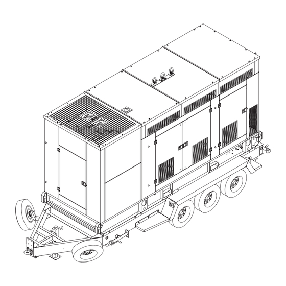
Oil leveler Emergency stop button Forklift pockets Main circuit breaker Battery (2) Control panel Fuel inlets (3/8 in LP fuel inlet and 2 in Catalyst (2) gaseous fuel inlet) Lifting eyes Manual holder Oil makeup filter Owner’s Manual for MGG450... -
Page 10: Specifications
Oil (including filter and reservoir tank) gal (L) 38 (144) Trailer Hitch — 3 in lunette ring Maximum Tire Pressure psi (kPA) 105 (724) Specifications are subject to change without notice. Refer to the product specification sheet for complete list. Owner’s Manual for MGG450... -
Page 11: Emissions Information
NOTE: For more detailed controller information, refer to Digital Controller the controller operator guide included with the unit. The MGG450 is equipped with a Motortech® All-In-One Cold Weather Starting Aids (Shore controller that monitors the unit and indicates operational Power) status and fault conditions. -
Page 12: Control Panel
AIO-NTC-BB (located behind panel): Main indicates unit is in auto, green indicates unit is in controller. auto and running on the specified fuel (gaseous or liquid). M Indicates the unit is currently operating on a liquid- LPG fuel source. Owner’s Manual for MGG450... -
Page 13: Engine Knock Intensity Screen
While most engines experience some knock during normal operation. If severity and duration are excessive, this can lead to engine damage. The MGG450 is equipped with knock sensors on every cylinder to detect and protect the engine from damaging knock conditions. - Page 14 NG solenoids (2) LPL lock-off valve LP vaporizers (2) M Service shut-off valve Primary pressure regulator Main pressure gauge Secondary pressure regulator Overpressure lock out device Cyclonic separator Secondary pressure gauge Coalescing filter Overpressure relief vent Mixer Owner’s Manual for MGG450...
-
Page 15: Natural Gas (Well Gas) Fuel System
Generator must be fully compatible with the rated voltage, phase rotation, and frequency of the connected electrical loads. The generator, connected electrical devices, or both, can be damaged if voltage, phase, and frequency are not compatible. Owner’s Manual for MGG450... -
Page 16: Lifting The Unit
Lift only from the side. Avoid approaching the unit at an angle, as this can permanently damage the forklift Lifting eye (4) pockets, tires, or cabinet. Verify any obstructions are Forklift pockets (4) clear of the forklift tines before lifting. Center hoist ring Owner’s Manual for MGG450... -
Page 17: Operation
47,000,000 J/kg prior to installation of the unit. A copy of the test report must be sent to, and pre-approved by, Generac Mobile Products. If the unit is moved to a new location, a new well test must be performed. For more information, contact Generac Mobile Products Technical Service. -
Page 18: Lp Liquid Connections (Liquid Withdrawal System)
– – – – 30 in. 22 in. 99 in. 75 in. 433 in. 344 in. 980 in. 794 in. 76 cm 56 cm 251 cm 191 cm 1100 cm 874 cm 2489 cm 2017 cm Owner’s Manual for MGG450... -
Page 19: Fuel Scrubbing System
• Verify unit is configured for the correct frequency (000151a) and voltage for the installation site. NOTE: Some installation environments are more corrosive than others. Be sure to follow all installation precautions, especially in high-humidity areas. Owner’s Manual for MGG450... -
Page 20: Starting The Generator
). If the fuel energy content is unknown, select hBTU ON and see step 8. NOTE: Only one gaseous fuel selection can be selected at a time. Multiple selections will default to the fuel selection with higher energy content. Owner’s Manual for MGG450... -
Page 21: Lp Liquid Only Operation
50 Hz file for the MGG450 must be uploaded to the AVR. 50 Hz Operation The MGG450 is capable of operating at either 60 Hz or Operation Checks 50 Hz. This is achievable by changing the basic settings... -
Page 22: Overcrank Shutdown
A fine mesh screen in the regulator provides protection rear door on the right side of the unit (see Figure 3-2). against damage by contaminants and abrasive foreign The bus bars provide connection points for attachment of matter. Owner’s Manual for MGG450... -
Page 23: Customer Convenience Receptacles
“earth ground” terminal. This ground is the normal operating conditions, pushing the “Open/Close local reference ground to ground the unit frame only. Breaker” button on the controller will switch the main circuit breaker CLOSE. Owner’s Manual for MGG450... -
Page 24: Paralleling Startup
Save configuration to AVR and close software. Parallel MGG450 to Other Gensets Paralleling Shutdown The MGG450 can be operated in parallel to other (non- Generac) gensets. The real portion (kW) of total electrical Completely unload generators and verify none of load will be divided among all gensets connected. -
Page 25: General Wiring Considerations
Quality (60 Hz units) Ambient Temperature Ambient Temperature Methane 77°F 86°F 95°F 104°F 113°F 122°F Number (25°C) (30°C) (35°C) (40°C) (45°C) (50°C) Methane 77°F 86°F 95°F 104°F 113°F 122°F Number (25°C) (30°C) (35°C) (40°C) (45°C) (50°C) Owner’s Manual for MGG450... -
Page 26: Towing The Trailer
Check the wheel lugs. Tighten or replace any that are loose or missing. If a tire has been removed or replaced, tighten lugs in the order shown in Figure 3-5. Owner’s Manual for MGG450... -
Page 27: Maintenance
LLC. recommends that all maintenance work be Accidental Start-up. Disconnect the negative battery cable, then the positive battery cable when working performed by a Generac Mobile Products Authorized on unit. Failure to do so could result in death Service Dealer (GMP ASD). Regular maintenance, or serious injury. -
Page 28: Basic Maintenance Schedule
Consult your GMP ASD • Check all flexible rubber hoses for deterioration. for oil recommendations. • Shell Mysell S5 N 15W40 (1500 hour change) • Valvoline Premium Blue GEO LA 15W40 (1500 hour change) Owner’s Manual for MGG450... -
Page 29: Check Engine Oil Level
Engine damage. Verify proper type and quantity of engine oil prior to starting engine. Failure to do so could result in engine damage. (000135) See the 1500 Hour Service Interval Manual (0L5448) for instructions on changing the engine oil. Owner’s Manual for MGG450... -
Page 30: Adding Coolant
• Use tools with insulated handles. (000188) • Wear rubber gloves and boots. • Do not lay tools or metal parts on top of battery. • Disconnect charging source prior to connecting or disconnecting battery terminals. Owner’s Manual for MGG450... -
Page 31: Battery Installation And Replacement
Doing so will result in equipment damage. (000167a) Connect battery cable from starter contactor to positive (POS or +) battery post. Connect black battery cable to negative (NEG or -) battery post. Refer to Starting the Generator. Owner’s Manual for MGG450... -
Page 32: Top-Wind Models
Use an appropriate thread sealant for the environment (temp ranges, fuel type, detergents, fuel oils etc.). Call Generac Mobile Products recommended sealant replacement parts if needed. Before operating the unit, perform a pressure test by opening the supply lock-off valve, allowing the system to pressurize, and then closing the supply lock-off valve. -
Page 33: Pressure Settings
Cold Weather Kit (if equipped) Automatic Filtration The MGG450 is available with or without a cold weather Both filters have an automatic drain. The coalescing filter kit. The manufacturer recommends installing the cold is equipped with a float valve which will automatically weather kit for operation of the unit at 40°F (4°C) or... -
Page 34: Operation
Pressure- 300psi 300psi Liquid propane Liquid propane Fuel Safety Resistive Fuel Safety Resistive Valves Heater Valves Heater Vaporizers Vaporizers SHORE SHORE Battery POWER Battery POWER Warmer SYSTEM Warmer SYSTEM 001729 Figure 4-3. Variable Pitch Automatic Fan Owner’s Manual for MGG450... -
Page 35: Troubleshooting
Technical Service. Engine fan or belts issues. Mechanical Noise Tighten flexplate to flywheel and Loose flexplate. alternator shaft. Throttle Does Not Move Battery not fully charged. Charge or replace battery. Oil Pan Over-Full Readjust Murphy fill. Owner’s Manual for MGG450... -
Page 36: Digital Controller Troubleshooting Guide
Verify calibration. Verify the interconnecting ribbon cable between the lexan faceplate Keypad Buttons (Switches) Keypad not connected to controller. and main printed circuit board is cor- Do Not Operate rectly connected. Replace control- ler if failed. Owner’s Manual for MGG450... -
Page 37: Digital Controller Alarm Abbreviations
InteliSys New Technology Basic Box (without display) KWP2000 Key Word Protocol of Scania S6 unit (for engine diagnostics) Logical Analog Inputs (card in GenConfig which is used to assign source signal to con- troller Logical Analog Input functions, e.g. Oil press) Owner’s Manual for MGG450... - Page 38 VAr Sharing - ensures VAr sharing between gen-sets on site via the CAN2 bus (for island parallel or mains parallel operation of multiple gen-sets) Voltage Transformer Setting of setpoints (with this character in front of them) is shared between controllers controllers via inter-controller CAN2 Owner’s Manual for MGG450...
-
Page 39: Digital Controller List Of Alarms
Bus voltage unbalance alarm is based on Gener protect (Bus protect): Bus Bus V unbal V unbal and Bus V unb del setpoints. The voltage unbalance is calculated as a maximum difference between phase voltages. Owner’s Manual for MGG450... - Page 40 BI: RunIndication 1 or 2 or 3 is active • Generator voltage > 15V (in any phase) Refer to Speed pick-up input section in the Technical data chapter in IGS- NT-x.y.-Installation Guide manual for information about requested pick-up signal parameters. Owner’s Manual for MGG450...
- Page 41 Actual state of synchronization is visible on the controller measurement screen with synchroscope where speed and voltage regulator's outputs, slip frequency and generator and mains voltages can be observed during the synchronization process. Owner’s Manual for MGG450...
- Page 42 ProtSel is set to PHASE-PHASE. Generator frequency was under the Gen <f limit for Gen f del time. Under BOC fgen under frequency protection is based on Gener protect: Gen <f and Gen f del set- points. Owner’s Manual for MGG450...
- Page 43 This alarm indicates wrong setpoints setting that disables start of genera- tors. Incorrect combination of ProcessControl: Island enable; ParallelEn- StartBlck able; Synchro enable; MF start enablesetpoints setting is the reason why this alarm is issued. Refer to OFF-MAN-AUT mode chapter in IM-NT- MCB-MGCB Reference Guide. Owner’s Manual for MGG450...
- Page 44 400 ms. Power format is set differently in controllers which are part of the same Wrn BadPwrCfg control group. Check Power formats setting in GenConfig on the Miscella- neous card (available in the Advanced mode only). Owner’s Manual for MGG450...
- Page 45 Indication of unsuccessful active call 1-3. Refer to Inteli Communication ActCallCH1Fail, CH2Fail, CH3- Guide for information about active calls. Refer to the IGSNT-x.y-Reference Fail Guide for description of setpoints which are part of the Act.calls/SMS group and are used for active call setup. Owner’s Manual for MGG450...
- Page 46 This could be due to a problem with the oxy- MAPControlFLS gen sensor, mixer, or intake air temperature. Contact Generac Mobile Products Technical Service for further diagnosis. Indicates an issue with emissions compliance. Contact Generac Mobile ChkEngP0134 Products Technical Service for further diagnosis.
-
Page 47: Wiring Diagrams And Service Log
Wiring Diagrams and Service Log Section 6 Wiring Diagrams and Service Log DC Controls (Page 1 of 6) Owner’s Manual for Generator... -
Page 48: Dc Controls
Wiring Diagrams and Service Log DC Controls (Page 2 of 6) Owner’s Manual for Generator... -
Page 49: Dc Controls
Wiring Diagrams and Service Log DC Controls (Page 3 of 6) Owner’s Manual for Generator... -
Page 50: Dc Controls
Wiring Diagrams and Service Log DC Controls (Page 4 of 6) Owner’s Manual for Generator... -
Page 51: Dc Controls
Wiring Diagrams and Service Log DC Controls (Page 5 of 6) Owner’s Manual for Generator... -
Page 52: Dc Controls
Wiring Diagrams and Service Log DC Controls (Page 6 of 6) Owner’s Manual for Generator... -
Page 53: Relay Connections
Wiring Diagrams and Service Log Relay Connections Owner’s Manual for Generator... -
Page 54: Ac Connections
Wiring Diagrams and Service Log AC Connections Owner’s Manual for Generator... -
Page 55: Control Panel Layout
Wiring Diagrams and Service Log Control Panel Layout Owner’s Manual for Generator... -
Page 56: Control Faceplate
Wiring Diagrams and Service Log Control Faceplate Owner’s Manual for Generator... -
Page 57: Can Wiring
Wiring Diagrams and Service Log CAN Wiring Owner’s Manual for Generator... -
Page 58: Receptacle
Wiring Diagrams and Service Log Receptacle Owner’s Manual for Generator... -
Page 59: Service Log
Wiring Diagrams and Service Log Service Log OIL GRADE: _____________________________________ BRAND: __________________________________ COOLANT MIXTURE: _____________________________ BRAND: __________________________________ __________________________________________________________________________________________ __________________________________________________________________________________________ __________________________________________________________________________________________ __________________________________________________________________________________________ __________________________________________________________________________________________ __________________________________________________________________________________________ __________________________________________________________________________________________ __________________________________________________________________________________________ __________________________________________________________________________________________ Hours to Coolant Hours to Coolant Date Oil Level Date Oil Level Service Level Service Level Owner’s Manual for Generator... - Page 60 ©2019 Generac Mobile Products, LLC Generac Mobile Products, LLC All rights reserved. 215 Power Drive, Berlin, WI 54923 Specifications are subject to change without notice. GeneracMobileProducts.com │800-926-9768 │920-361-4442 No reproduction allowed in any form without prior written consent from Generac Mobile Products, LLC.
Need help?
Do you have a question about the MGG450 and is the answer not in the manual?
Questions and answers