
Related Manuals for peerless-AV PC575-UNL


Summary of Contents for peerless-AV PC575-UNL
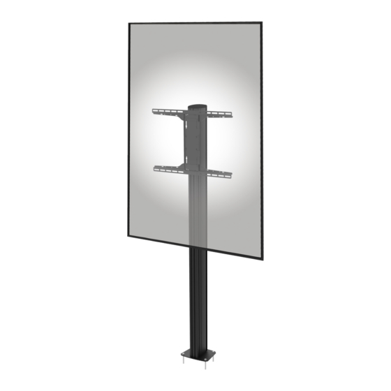
- Page 1 PC575-UNL Universal In-Window Bolt-Down 32" to 75" Max Load Up to VESA 60kg (132lbs) 600 x400mm 2024-03-08 #:059-9015-1 (rev.1)
- Page 2 WARNING ENG - This product is designed to be installed on solid concrete. Hardware is included for solid concrete installation. Before installing make sure the supporting surface will support the combined load of the equipment and hardware. Screws must be tightly secured. Do not overtighten screws or damage can occur and product may fail.
- Page 3 Tools Needed for Assembly. Outils nécessaires au montage. Für den Zusammenbau erforderliche Werkzeuge. 1/2" (12mm) 3/8" (10mm) WARNING ADVERTISSEMENT To properly tighten screws: Tighten until ACHTUNG screw head makes contact, then tighten another 1/2 turn. Do not overtighten screws. Pour bien serrer les vis : Serrez jusqu’à ce que la tête de la vis entre en contact, puis serrez encore d’un 1/2 tour.
- Page 4 Parts (Before beginning, make sure you have all parts shown on the included configuration diagram for your specific configuration). Avant de commencer, assurez-vous que vous disposez de toutes les pièces indiquées sur le schéma de configuration inclus pour votre configuration spécifique) Vergewissern Sie sich, bevor Sie beginnen, dass Sie alle Teile haben, die auf dem beiliegenden Konfigurationsdiagramm für Ihre spezifische Konfiguration gezeigt werden) Parts List...
- Page 5 Flat Base Plate Installation Components Part# Description Qty per Assembly KP-FBP Flat Base Plate Kit Base Plate Concrete Floor Anchor M8 x 45mm Base Plate Concrete M8 x 45mm Floor Anchor Position base plate relative to the required display placement. Align and mark hole positions Positionnez la plaque par rapport à...
- Page 6 Fix flat base plate to the bottom of extrusion column (A). Fixez la plaque de la base au bas de la colonne d'extrusion (A). Befestigen Sie die Bodenplatte an der Unterseite der Führungssäule (A). Align base to drilled holes and install using concrete anchors provided.
- Page 7 Universal Screen Adaptor Installation Parts List Part # Description Quantity MOD-UNL Universal Screen Adaptor Kit 096-1437 Vertical Plate 096-1439 Horizontal Plate 096-1440 Plate Nut 520-1063 M5 x 10mm screw 600-1215 6mm Height Spacer 520-1079 M4 x 12mm 520-1082 M4 x 25mm 520-1050 M6 x 12mm 520-1211...
- Page 8 24.37" (619mm) X = 100-200mm X = 200-300mm X = 300-400mm 2a-1 2b-1 2c-1 2a-1 2b-1 2c-1 2024-03-08 #:059-9015-1 (rev.1)
- Page 9 2a-1 2b-1 2c-1 CB (2) CB (2) CB (2) 2c-2 2a-2 2b-2 Do not tighten the screws. Do not tighten the screws. Do not tighten the screws. Ne serrez pas les vis. Ne serrez pas les vis. Ne serrez pas les vis. Ziehen Sie die Schrauben Ziehen Sie die Schrauben Ziehen Sie die Schrauben...
- Page 10 Use of spacers and washers is optional. Facultatif utilisation d’entretoises de rondelles. Fakultativ verwendung von abstandhaltern und Waschmaschinen. CE (2) CE (2) CM (2) CI,CK,CO 2024-03-08 #:059-9015-1 (rev.1)
- Page 11 Tighten. Serrer. Anziehen. Do not tighten fully 2024-03-08 #:059-9015-1 (rev.1)
- Page 12 Attach slide blocks to the adaptor bracket using fixings provided. Do not tighten fully at this stage. Installez les patins sur le support à l'aide des vis prévues à cet effet. Ne pas trop serrer à ce stade. Befestigen Sie die Schiebeblöcke mit den mitgelieferten Befestigungen am Adapterhalter.
- Page 13 Hook fixing bolts on the rear of the MOD-UNL adaptor into the keyhole slots at the top of the adaptor bracket on the extrusion column. Placez les vis à l'arrière de l'adaptateur MOD-UNL dans les ouvertures en forme de trou de serrure situées en haut du support de l'adaptateur sur la colonne d'extrusion.
- Page 14 Run cables, then attach 'push-fit' cable management covers to the rear of vertical extrusions. Insert end cap into top of vertical extrusion. Faire passer les câbles, puis clipser les cache-câbles "push-fit" à l'arrière des profilés verticaux. Verlegen Sie die Kabel und befestigen Sie dann die Abdeckungen für das Kabelmanagement an der Rückseite der vertikale Profile.
-
Page 15: Limited Five-Year Warranty
(from date of the original installation of the product). At its option, Peerless-AV will repair or replace, or refund the purchase price of, any product which fails to conform with this warranty. - Page 16 Peerless-AV Peerless-AV Europe Peerless-AV América Latina 2300 White Oak Circle Unit 2 Curo Park, Av. de las Industrias 413 Aurora, IL 60502 Frogmore, St Albans Parque Industrial Escobedo Email: tech@peerlessmounts.com AL2 2DD, United Kingdom General Escobedo N.L., México 66062 Ph: (800) 865-2112...
Need help?
Do you have a question about the PC575-UNL and is the answer not in the manual?
Questions and answers