Table of Contents
Advertisement
Available languages
Available languages
Quick Links
Installation and Assembly:
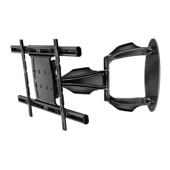
Universal Articulating Arm Wall Mount for 32" to 52" Flat Panel
Displays
Models: SA752PU / PEWS350/BK
Max UL Load Capacity: 90 lb (41.82 kg)
2300 White Oak Circle • Aurora, Il 60502 • (800) 865-2112 • Fax: (800) 359-6500 • www.peerlessmounts.com
ISSUED: 10-30-09 SHEET #: 095-9297-7 07-11-11
Advertisement
Chapters
Table of Contents

Related Manuals for peerless-AV SA752PU


Summary of Contents for peerless-AV SA752PU
- Page 1 Universal Articulating Arm Wall Mount for 32" to 52" Flat Panel Displays Models: SA752PU / PEWS350/BK Max UL Load Capacity: 90 lb (41.82 kg) 2300 White Oak Circle • Aurora, Il 60502 • (800) 865-2112 • Fax: (800) 359-6500 • www.peerlessmounts.com...
-
Page 2: Table Of Contents
Note: Read entire instruction sheet before you start installation and assembly. WARNING • Do not begin to install your Peerless product until you have read and understood the instructions and warnings contained in this Installation Sheet. If you have any questions regarding any of the instructions or warnings, for US customers please call Peerless customer care at 1-800-865-2112, for all international customers, please contact your local distributor. -
Page 3: Parts List
Before you begin, make sure all parts shown are included with your product. Parts List SA752PU Description Qty. Part # A wall arm assembly 095-P1715 B universal adapter bracket 095-P1635-2 C wood screws 520-1202 D concrete anchors 590-0320 E M10 x 15 mm socket head screw... - Page 4 Adapter Bracket Fasteners M5 x 12mm (4) M4 x 12mm (6) (520-1027) M6 x 12mm (4) (504-9013) M5 x 25mm (4) M6 x 20mm (4) (520-1128) (520-9543) (520-9402) M6 x 25mm (4) M4 x 25mm (4) (520-1208) (504-1015) I.D. .22" (4) (540-1057) I.D.
-
Page 5: Wall Installation
Installation to Single Wood Stud Wall WARNING • Installer must verify that the supporting surface will safely support the combined load of the equipment and all attached hardware and components. • Tighten wood screws so that wall plate is fi rmly attached, but do not overtighten. Overtightening can damage the screws, greatly reducing their holding power. - Page 6 Installation to Solid Concrete or Cinder Block WARNING • When installing Peerless wall mounts on cinder block, verify that you have a minimum of 1-3/8" (35mm) of actual concrete thickness in the hole to be used for the concrete anchors. Do not drill into mortar joints! Be sure to mount in a solid part of the block, generally 1"...
-
Page 7: Installing Adapter Brackets To Display
Installing Adapter Brackets to Display NOTE: If display has a VESA 400 horizontal mounting pattern, skip to step 2-3 or 2-4 on page 9. NOTE: For VESA 200x200 or VESA 200x100 mount hole patterns, skip to step 3 on page 10. 1/4-20 x 1.25"... - Page 8 Installing Adapter Brackets to Display WARNING • Tighten screws so display brackets are fi rmly attached to display. Do not tighten with excessive force. Overtightening can cause stress damage to screws, greatly reducing their holding power and possibly causing screw heads to become detached. Tighten to 40 in. • lb (4.5 N.M.) maximum torque. •...
- Page 9 For Flat Back Display Begin with the shortest length screw, hand thread DISPLAY screw through multi-washer and display brackets (B) into display as shown below. Screw must make MULTI-WASHER at least three full turns into the mounting hole and fi t snug into place. Do not over tighten. If screw SCREW cannot make three full turns into the display, select a longer length screw from the baffl...
- Page 10 VESA 200 x 200 or VESA 200 x 100 Mounting Pattern Remove four 1/4-20 x .6" screws using 5mm allen wrench (I) and loosen two 1/4-20 x 1.25" screws 1/2 turn to allow for display bracket adjustment. 1/4-20 x 1.25" SCREWS 1/4-20 x .6"...
- Page 11 VESA 200 x 200 or VESA 200 x 100 Mounting Pattern (Continued) Align one display bracket with one set of display DISPLAY mounting holes. SCREW MULTI- Begin with the shortest length screw, hand thread WASHER screw through multi-washer and display brackets into display as shown.
-
Page 12: Mounting Flat Panel Display
Mounting Flat Panel Display WARNING • Do not lift more weight than you can handle. Use additional man power or mechanical lifting equipment to safely handle placement of the display. • Do not tighten screws with excessive force. Overtightening can cause damage to mount. Tighten M10 x 15mm screws (E) to 40 in. - Page 13 Adjustment of Flat Panel Display WARNING • M10 x 15mm screws (E) must be securly tightened before changing orientation of wall arm (A). Failure to lock adapter bracket can cause display to come off of mount. FOR PORTRAIT OR LANDSCAPE DISPLAY ORIENTATION: Remove two M5 x 12mm screws, one M5 x 6mm screw and rotation block from top of tilt head as shown in top view and rear view.
-
Page 14: Cable Management
Cable Management NOTE: Make sure cables have enough slack to allow full movement of the arm. Run power cable through top or bottom of wall arm (A) and signal cable(s) through other side of arm in order to avoid interference with the signal. Lock cables into place by snapping cable covers (J & K) onto mount. Display may have to be moved for easy access. - Page 15 Soportes de pared de brazo articulador para pantallas planas de 32" a 52" Modelos: SA752PU / PEWS350/BK Máxima capacidad de carga para UL: 90 lb (41.82 kg) 2300 White Oak Circle • Aurora, Il 60502 • (800) 865-2112 • Fax: (800) 359-6500 • www.peerlessmounts.com...
- Page 16 Español NOTA: Lea la hoja de instrucciones completa antes de comenzar la instalación y el ensamblaje. ADVERTENCIA • No comience a instalar su producto de Peerless hasta haber leído y entendido las instrucciones y las advertencias contenidas en la Hoja de Instalación. Si tiene alguna pregunta acerca de cualquiera de las instrucciones o las ad- vertencias, por favor, llame a Servicio al Cliente de Peerless al 1-800-865-2112 si está...
-
Page 17: Lista De Piezas
Español Antes de empezar, asegúrese de que todas las piezas que se muestran son incluidos con su producto. Lista de piezas SA752PU Descripción Cant. Nº de pieza A brazo de pared 095-P1715 B soporte adaptador universal 095-P1635-2 C tornillos para madera... - Page 18 Español Fijaciones para los soportes adaptadores M5 x 12mm (4) M4 x 12mm (6) (520-1027) M6 x 12mm (4) (504-9013) M5 x 25mm (4) M6 x 20mm (4) (520-1128) (520-9543) (520-9402) M6 x 25mm (4) M4 x 25mm (4) (520-1208) (504-1015) I.D.
-
Page 19: Instalación En Una Pared
Español Instalación en una pared con montante de madera único ADVERTENCIA • El instalador debe verifi car que la superfi cie de apoyo sea capaz de soportar fi rmemente la carga combinada del equipo y todos los herrajes y componentes. •... - Page 20 Español Instalación en una pared de concreto macizo o de bloques de hormigón de escorias ADVERTENCIA • Cuando instale soportes de pared Peerless en bloques de hormigón de escorias, verifi que que tengan un mínimo de 1-3/8" (35mm) de superfi cie efectiva de concreto en el agujero que va a utilizar para los anclajes de concreto. ¡No perfore en las juntas de mortero! Asegúrese de instalar el soporte en una parte sólida del bloque, generalmente a un mínimo de 1"...
- Page 21 Español Instalación de los soportes adaptadores NOTA: Si la pantalla tiene una confi guración de montaje horizontal VESA 400, proceda al paso 2-3 o al 2-4 de la página 23. NOTA: Si la pantalla tiene una confi guración de TORNILLOS 1/4-20 x 1.25" montaje horizontal VESA 200x200 o VESA 200 x 100, proceda al paso 3 de la página 24.
- Page 22 Español Instalación de los soportes adaptadores ADVERTENCIA • Apriete los tornillos de tal modo que los soportes adaptadores queden fi rmemente sujetos. No apriete aplicando demasiada fuerza. El apriete excesivo puede causar daño por esfuerzo a los tornillos, reduciendo enormemente su fuerza de fi jación y causando el posible desprendimiento de sus cabezas.
- Page 23 Español Instalación de un televisor que tiene la parte posterior plana Comience con uno de los tornillos más cortos, PANTALLA enrósquelo, con la mano, a través de la arandela ARANDELA MÚLTIPLE múltiple y el soporte de la pantalla (B) a la parte posterior de la pantalla, como se muestra abajo.
- Page 24 Español VESA 200 x 200 o VESA 200 x 100 Patrón de montaje Quite los cuatro tornillos de 1/4-20 x .6" utilizando una llave allen de 5mm (I) y afl oje los dos tornillos de 1/4-20 x 1.25" TORNILLOS 1/4-20 x 1.25" 1/2 vuelta para poder ajustar el soporte de la pantalla.
- Page 25 Español VESA 200 x 200 o VESA 200 x 100 Patrón de montaje (continuacion) Alinee uno de los soportes de la pantalla con PANTALLA TORNILLO uno de los grupos de agujeros de montaje de la ARANDELA pantalla. MÚLTIPLE Comience con el tornillo de longitud más corta, SOPORTES la mano de rosca a través de múltiples soportes DE LA...
-
Page 26: Instalación Del Soporte Adaptador Universal
Español ADVERTENCIA • No levante más peso del que puede manejar. Cuente con otra persona que lo ayude o utilice un equipo mecánico de izar para levantar y colocar la pantalla con seguridad. • No apriete los tornillos con fuerza excesiva. Apretarlos en exceso puede dañar el soporte. Apriete los tornillos M10 x 15mm (E) a un máximo de 40 pulg-lb (4.5 N•m) de par torsor. - Page 27 Ajuste de la Pantalla Plana Español ADVERTENCIA Trabar la placa de pared montaje (A) con los tornillos M10 x 15mm (E) antes de cambiar la orientación. Puede • causar que la pantalla se desprenda de la unidad de soporte si le dan un golpe accidentalmente. PARA COLOCAR LA PANTALLA VERTICAL U HORIZONTALMENTE: Quite los dos tornillos de M5 x 12mm, una tornillos de M5 x 6mm y el bloque rotatorio de la parte superior del cabezal inclinable, como se muestra en la vista superior y en la vista trasera.
-
Page 28: Manejo De Los Cables
Español Manejo de cables NOTA: Asegúrese de que los cordones no queden muy cortos para que el brazo se pueda mover completamente. Pase el cordón de la electricidad por la parte superior o la parte inferior del brazo (A) y el cable o los cables de la señal por el otro lado del brazo para evitar que haya interferencia con la señal. - Page 29 Montants muraux pour écrans plats articulés pour écrans de 32 à 52 pouces Modèles: SA752PU / PEWS350/BK Capacité de charge UL maximale: 90 lb (41.82 kg) 2300 White Oak Circle • Aurora, Il 60502 • (800) 865-2112 • Fax: (800) 359-6500 • www.peerlessmounts.com PUBLIÉ...
- Page 30 Français REMARQUE: lisez entièrement la fi che d’instructions avant de commencer l’installation et l’assemblage. AVERTISSEMENT • Ne commencez pas à installer votre produit Peerless avant d’avoir lu et assimilé les instructions et les avertisse- ments contenus dans cette fi che d’installation. Pour toute question concernant les instructions ou les avertissements, veuillez appeler le service à...
-
Page 31: Liste Des Pièces
Français Avant de commencer, s'assurer que toutes les pièces indiquées sont incluses avec le produit. Liste des pièces SA752PU Description Qté Pièce nº A bras mural 095-P1715 B adaptateurs universels 095-P1635-2 C vis à bois 520-1202 D concreto d’ancrage 590-0320... - Page 32 Français Fixations du support adaptateur M5 x 12mm (4) M4 x 12mm (6) (520-1027) M6 x 12mm (4) (504-9013) M5 x 25mm (4) M6 x 20mm (4) (520-1128) (520-9543) (520-9402) M6 x 25mm (4) M4 x 25mm (4) (520-1208) (504-1015) I.D.
-
Page 33: D'installation Au Mur
Français Installation sur un mur à montant en bois AVERTISSEMENT • L’installateur doit s’assurer que la surface de support pourra soutenir sans danger la charge combinée de l’équipement, de toute sa visserie et de tous ses composants. • Serrez les vis à bois de manière que la plaque murale soit fermement fi xée, mais sans excès. Un serrage excessif peut endom- mager les vis et en réduire considérablement le pouvoir de maintien. - Page 34 Français Installation sur du béton plein ou un bloc de béton de mâchefer AVERTISSEMENT • Si vous installez des montures murales Peerless sur un bloc de béton de mâchefer, vérifi ez que vous disposez d’une épaisseur de béton d’au moins 35mm (1 3/8 po) dans le trou destiné aux ancrages de béton. Ne percez pas dans les joints de mortier ! Veillez à...
-
Page 35: D'installation Du Support Adaptateur Universel
Français Installation des Supports Adaptateurs à l'écran REMARQUE : Si l'écran possède une confi guration de trous de montage horizontaux VESA 400, pas- sez à l'étape 2-3 ou 2-4 en page 37. REMARQUE : Si l'écran possède une confi guration VIS 1/4-20 X 1.25 PO de trous de montage horizontaux VESA 200x200 ou VESA 200x100, passez à... - Page 36 Français Installation des Supports Adaptateurs à l'écran AVERTISSEMENT • N’employez pas une force excessive pour serrer les vis. Un serrage excessif peut endommager le support. Serrez les vis à un couple maximum de 4,5 Nm (40 po-lb). • Si les vis ne sont pas enfoncées de trois tours complets dans les inserts ou si elles sont serrées au maximum sans parvenir à fi...
- Page 37 Français Pour les écrans à dos plat Commencez par la vis la plus courte et vissez- ÉCRAN la manuellement à l’écran en la faisant passer à RONDELLE travers la rondelle tout-usage et les supports de UNIVERSELLE l'écran (B), comme indiqué ci-dessous. La vis doit effectuer au moins trois tours complets dans le trou de fi...
- Page 38 Français VESA 200 x 200 ou VESA 200 x 100 Modèle de montage Retirez quatre vis 1/4-20 x 0,6 po à l'aide d'une clé hexagonale de 5mm (I) et desserrez deux vis 1/4-20 x 1,25 po d'un demi-tour pour permettre le VIS 1/4-20 X 1.25 PO réglage du support de l'écran.
- Page 39 Français VESA 200 x 200 ou VESA 200 x 100 Modèle de montage (suite) Alignez un support d'écran avec un ensemble de ÉCRAN trous de fi xation de l'écran. RONDELLE Commencez par la vis la plus courte et vissez- UNIVERSELLE la manuellement à...
-
Page 40: Installation De L'écran Plat
Français AVERTISSEMENT • Ne soulevez pas plus que votre capacité. Faites-vous aider par une autre personne ou utilisez un système de levage mécanique pour effectuer une installation de l’écran en toute sécurité. • Ne serrez pas les vis de façon excessive. Un serrage excessif peut endommager le montant. Serrez les vis M10 x 15mm (E) à un couple maximal de 40 po-lb (4,5 N.m). - Page 41 Réglage d’un écran plat Français AVERTISSEMENT • Si le plaque murale (A) n’est pas verrouillé avec deux vis M10 x 15mm (E) avant que l'orientation est changée, l’écran peut se détacher du montant s’il est heurté accidentellement. ORIENTATION DE L'ÉCRAN SELON UN FORMAT VERTICAL OU HORIZONTAL : Retirez les deux vis M5 x 12mm, vis M5 x 6mm et le bloc de rotation de la partie supérieure de la tête basculante comme illustré...
-
Page 42: Gestion Des Câbles
Français Gestion des câbles Remarque : Veillez à ce que les câbles aient assez de jeu pour permettre au bras de bouger librement. Acheminez le câble d'alimentation dans le haut ou le bas du bras (A) et le(s) câble(s) d'interconnexion dans l'autre côté... - Page 43 Anbringung und Zusammenbau: Gelenkarm-Wandhalter für Flachbildschirme von 32 - 52 Zoll Modelle: SA752PU / PEWS350/BK Maximale UL Tragfähigkeit: 90 lb (41.82 kg) 2300 White Oak Circle • Aurora, Il 60502 • (800) 865-2112 • Fax: (800) 359-6500 • www.peerlessmounts.com AUSGEGEBEN: 10-30-09 BLATT NR.: 095-9297-7 07-11-11...
- Page 44 Deutsch HINWEIS: Lesen Sie die gesamte Anleitung, bevor Sie mit der Anbringung und dem Zusammenbau beginnen. ACHTUNG • Beginnen Sie mit der Anbringung Ihres Peerless-Produkts erst, nachdem Sie die in dieser Montageanleitung enthaltenen Anleitungen und Achtungshinweise gelesen und sich gründlich mit ihnen vertraut gemacht haben. Falls Sie Fragen hinsichtlich irgendeiner der Anleitungen oder Achtungshinweise haben, wenden Sie sich in den USA bitte an den Peerless-Kundendienst unter der Rufnummer 1-800-865-2112.
-
Page 45: Teileliste
Deutsch Bevor Sie beginnen, stellen Sie sicher, alle Teile gezeigt, mit Ihrem Produkt enthalten sind. Teileliste SA752PU Beschreibung Anz. Teile Nr. A Wandarm 095-P1715 B Universell-Adapterhalterung 095-P1635-2 C Holzschrauben 520-1202 D Beton Dübel 590-0320 E M10 x 15 mm Schrauben... - Page 46 Deutsch Befestigungsteile Für Adapterhalterung M5 x 12mm (4) M4 x 12mm (6) (520-1027) M6 x 12mm (4) (504-9013) M5 x 25mm (4) M6 x 20mm (4) (520-1128) (520-9543) (520-9402) M6 x 25mm (4) M4 x 25mm (4) (520-1208) (504-1015) I.D. .22" (4) (540-1057) Mehrlochs- I.D.
-
Page 47: Anbringung An Wand
Deutsch Anbringung an Wänden mit einer Holzständerreihe ACHTUNG • Bei der Anbringung muss darauf geachtet werden, dass die Wand die kombinierte Last von Bildschirm und allen Befestigungsteilen und -komponenten tragen kann. • Ziehen Sie die Schrauben fest genug an, dass die Wandplatte sicher befestigt ist, doch ohne sie zu überdrehen. Durch Überdrehen können die Schrauben beschädigt werden, wodurch ihr Haltevermögen stark reduziert wird. - Page 48 Anbringung an Massivbeton oder Porenbetonstein Deutsch ACHTUNG • Bei der Anbringung von Peerless-Wandhaltern an Porenbetonstein muss sichergestellt werden, dass die tatsächliche Stärke des Betons, in den das Loch für die Betondübel gebohrt wird, mindestens 35mm (1 3/8 Zoll) beträgt. Bohren Sie nicht in Mörtelfugen! Achten Sie darauf, dass die Anbringung an einem massiven Teil des Blocks erfolgt, im Allgemeinen mindestens 25mm (1 Zoll) von der Blockseite entfernt.
-
Page 49: Anbringung Der Adapterhalterung Am Bildschirm
Deutsch Installation Adapterhalterungen zur Bildschirmansicht HINWEIS: Wenn der Bildschirm über das Montage- muster VESA 400 verfügt, fahren Sie mit Schritt 2-3 oder 2-4 auf Seite 51 fort. 1/4-20 x 1.25 ZOLL HINWEIS: Wenn der Bildschirm über das Montage- SCHRAUBEN muster VESA 200x200 oder VESA 200x100 verfügt, fahren Sie mit Schritt 3 auf Seite 52 fort. - Page 50 Deutsch Installation Adapterhalterungen zur Bildschirmansicht ACHTUNG • Ziehen Sie die Schrauben nicht zu fest an. Durch Überdrehen kann der Halter beschädigt werden. Das maximale Drehmoment zum Festziehen der Schrauben darf 40 in • lb (4,5 Nm) nicht überschreiten. • Sind die Schrauben nicht um drei volle Umdrehungen in die Löcher des Bildschirms eingeschraubt oder stoßen sie unten an und die Halterung ist noch immer nicht sicher befestigt, kann der Bildschirm beschädigt werden oder das Produkt kann versagen.
- Page 51 Deutsch Bildschirme mit fl acher Rückseite Beginnen Sie mit der kürzesten Schraube und schrauben Sie diese wie unten dargestellt BILDSCHIRM von Hand durch die Mehrlochscheibe und MEHRLOCHSCHEIBE Bildschirmhalterungen (B) in den Bildschirm. Die Schraube muss sich um mindestens drei volle SCHRAUBE Umdrehungen in die Montagebohrung drehen lassen und gut festsitzen.
- Page 52 Deutsch VESA 200 x 200 oder 200 x 100 VESA Montage-Muster Entfernen Sie mithilfe des 5mm Inbusschlüssels (I) die vier 1/4-20 x 0,6 Zoll Schrauben und 1/4-20 x 1.25 ZOLL lösen Sie zwei 1/4-20 x 1,25 Zoll Schrauben um SCHRAUBEN eine halbe Umdrehung, um das Einstellen der Bildschirmhalterung zu ermöglichen.
- Page 53 Deutsch VESA 200 x 200 oder 200 x 100 VESA Montage-Muster (Fortsetzung) Richten Sie eine Bildschirmhalterung mit einer BILDSCHIRM Gruppe von Bildschirm-Montagebohrungen aus. SCHRAUBE Beginnen Sie mit der kürzesten Schraube MEHRLOCHSCHEIBE Linksgewinde Schraube durch multi-Scheibe und Bildschirmhalterungen in den Bildschirm wie BILDSCHIRM- abgebildet.
-
Page 54: Anbringung Des Flachbildschirms
Deutsch ACHTUNG • Ziehen Sie immer eine zusätzliche Person heran oder verwenden Sie mechanische Hebegeräte, um den F lachbildschirm sicher zu heben und zu positionieren. • Ziehen Sie die Schrauben nicht zu fest an. Durch Überdrehen kann der Halter beschädigt werden. Das maximale Drehmoment zum Festziehen der M10 x 15mm Schrauben (E) darf 40 in •... - Page 55 Einstellung des Flachbildschirms Deutsch ACHTUNG Adapterplatte (A) • Wenn der nicht mit M10 x 15mm Schrauben ( ) gesichert und arretiert wird, kann der Bildschirm bei versehentlichem Anstoßen vom Halter herabfallen. AUSRICHTEN DES BILDSCHIRMS IM HOCH- ODER QUERFORMAT: Entfernen Sie zwei M5 x 12mm Schrauben, M5 x 6mm Schrauben und den Drehblock von der Oberseite des Neigungskopfs wie in der Draufsicht und Rückansicht dargestellt.
-
Page 56: Kabelführung
Kabelführung Deutsch Hinweis: Achten Sie darauf, dass die Kabel ausreichend durchhängen, damit der Arm in vollem Umfang bewegt werden kann. Verlegen Sie das Netzkabel oben oder unten durch den Arm (A) und das (die) Signalkabel auf der anderen Seite, um Signalstörungen zu verhindern. Sichern Sie die Kabel, indem Sie die Kabelabdeckungen (J und K) auf den Halter drücken. - Page 57 LIMITED FIVE-YEAR WARRANTY Peerless Industries, Inc. (“Peerless”) warrants to original end-users of Peerless® products will be free from defects in material and workmanship, under normal use, for a period of fi ve years from the date of purchase by the original end-user (but in no case longer than six years after the date of the product’s manufacture). At its option, Peerless will repair or replace, or refund the purchase price of, any product which fails to conform with this warranty.
- Page 58 Français GARANTIE DE CINQ ANS Peerless Industries, Inc. (« Peerless ») garantit aux utilisateurs fi naux d’origine des produits PeerlessMD que lesdits produits ne présenteront aucun défaut de matériau ou de main-d’œuvre, dans la mesure où ils sont utilisés normalement, pendant une période de cinq ans à compter de la date d’achat par l’utilisateur fi nal d’origine (mais en aucun cas plus de six ans après la date de fabrication du produit).
Need help?
Do you have a question about the SA752PU and is the answer not in the manual?
Questions and answers