Table of Contents
Advertisement
Quick Links
Thank you for trusting Prestige products! If you are a consumer, please note:
Professional installation is strongly recommended.
This manual assumes the installer has adequate knowledge of the following expertise. Therefore, it does not
cover these topics in detail:
•
12-volt electronics
•
Testing and verifying circuits
•
Making safe and lasting wiring connections
•
Factory ignition, power, lighting, data bus and sensing systems
•
Factory systems and components to avoid
•
Safe wire routing, circuit protection and product placement
•
Access to vehicle-specific technical information
In addition, this manual assumes the installer has the proper tools, skill and facilities to perform a professional installation.
Performing an improper installation could result in damage to the vehicle or its components, improper system function,
unsafe vehicle operation or physical injury. Such instances would not be covered by the vehicle manufacturer's warranty,
nor by Voxx Electronics, Inc.
2
Wire Harness Colors and Functions
2
3
6
6
6
RF Antenna Kit
6
6
Telematics
7
7
8
12
Negative Output Control (NOC)
14
AUX Output Control
15
PIC Input Control
16
16
2020 Voxx Electronics Corporation. All rights reserved.
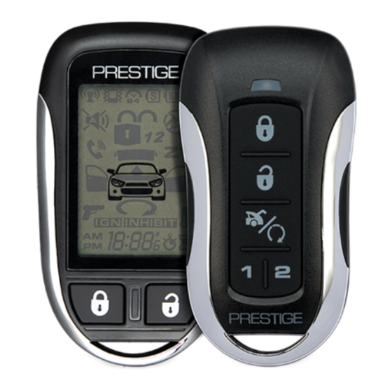
APS596Z
Vehicle Security / Keyless Entry System
Installation and Reference Guide
17
System Programming
17
Programming Mode Entry / Exit
18
18
19
19
19
19
System Diagnostics
19
19
20
Alarm Override Procedures
21
Wiring Diagrams
21
24
Starter Kill Relay
25
Full System Connections
APS596Z_RevB_07/20
Advertisement
Table of Contents

Related Manuals for Prestige APS596Z


Summary of Contents for Prestige APS596Z
-
Page 1: Table Of Contents
Vehicle Security / Keyless Entry System Installation and Reference Guide Thank you for trusting Prestige products! If you are a consumer, please note: Professional installation is strongly recommended. This manual assumes the installer has adequate knowledge of the following expertise. Therefore, it does not cover these topics in detail: •... -
Page 2: Detailed Descriptions
Detailed Descriptions: Wire Harness Colors and Functions Power / Notification Connector (6-pin connector) See page 25 for the full system diagram. These wires are listed in order of their placement in the harness connector. 1 3 5 2 4 6 1. -
Page 3: Input / Output Connector
Detailed Descriptions: Wire Harness Colors and Functions Input / Output Connector (20-pin connector) See page 25 for the full system diagram. These wires are listed in order of their placement in the harness connector. 10 12 14 16 18 20 1. - Page 4 Detailed Descriptions: Wire Harness Colors and Functions Input / Output Connector (20-pin connector) (Cont.) See page 24 for the full system diagram. These wires are listed in order of their placement in the harness connector. 8. LIGHT GREEN – Trunk / Hatch Input (-) (PIC 2) The LIGHT GREEN wire connects a device or switch that, when triggered, supplies a Ground (-) output.
- Page 5 Detailed Descriptions: Wire Harness Colors and Functions Input / Output Connector (20-pin connector) (Cont.) See page 24 for the full system diagram. These wires are listed in order of their placement in the harness connector. 17. BLACK/WHITE – Horn Output (-) (NOC 9) The BLACK/WHITE wire connects to the vehicle's horn wire and supplies Ground (-) when activated from the system.
-
Page 6: External Components
Shock Sensor The shock sensor plugs into a 4-pin connector on the Prestige module. It should be securely attached to a vehicle surface or sturdy wire harness. Testing takes place after all connections are made and the system is powered up. Refer to Quick Reference: System Diagnostics on page 19 for instructions on testing and adjusting the shock sensor. -
Page 7: Setup Options
Detailed Descriptions: Setup Options Bank 1: Add / Remove Remote Controls Remote programming is located in Feature Bank 1. This system will Auto Program basic functions of the remote with one (1) button press. Basic functions are channels 1-3, Lock, Unlock, and Trunk / Start. Feature Bank 1 Description 1 Auto Program/Lock... -
Page 8: Security Control
Detailed Descriptions: Setup Options Security Control (Bank 2) See page 17 for Programming Instruction. Op�ons Features 1 Chirp 2 Chirp 3 Chirp 4 Chirp 5 Chirp 6 Chirp 1 Lock / Unlock Func�on 500ms 3.5sec 500ms L, DBL UL DBL L, 500ms UL DBL L, DBL UL 500ms L, 350ms UL 2 Igni�on Lock... - Page 9 Detailed Descriptions: Setup Options Security Control (Bank 2) (cont.) See page 17 for Programming Instruction. Feature 4: Exterior Illumination Function: Set the parking lights and head lights to remain on for 30 seconds when the doors are locked or unlocked with the remote control.
- Page 10 Detailed Descriptions: Setup Options Security Control (Bank 2) (Cont.) See page 17 for Programming Instruction. Feature 9: Override Method Function: Set the Alarm Override Method. This will be used if the Remote is lost or inoperable. Setting Choices: • Option 1 - Alarm Override method is normal. Ignition Key ON, press Valet button 1x •...
- Page 11 Detailed Descriptions: Setup Options Security Control (Bank 2) (Cont.) See page 17 for Programming Instruction. Feature 15: Data Bus (DBI) Port Protocol Function: Set functionality of the data bus connector to accept integration modules of differing protocols. Setting Choices: • Option 1 - The data bus connector will be configured to work with modules that use the ADS Protocol.
- Page 12 Detailed Descriptions: Setup Options Security Control (Bank 2) (Cont.) See page 17 for Programming Instruction. Feature 21: Disarm 2 Input Polarity Function: Set the Disarm 2 input polarity Setting Choices: • Option 1 - System will Auto Detect the input polarity on power-up . •...
- Page 13 Detailed Descriptions: Setup Options NOC Outputs (Negative Output Control) Negative Output Control (NOC) allows the installer to program any NOC output for any NOC option. For example, if an installer is not using the GREEN/WHITE Dome Light output, but requires a second Unlock Output, the system can be programmed to change the output timing.
- Page 14 Detailed Descriptions: Setup Options Ch. 7 AUX This option will supply an output when the AUX 4 function is pressed on the remote control or CarLink system. See page 18 for AUX Output Options. Ground While Armed (GWA) This option will supply an output when the Alarm System is Armed. Ground While Disarmed (GWD) This option will supply an output when the Alarm System is Disarmed.
-
Page 15: System Operation
Detailed Descriptions: System Operation Programmable Input Control (PIC Control) Programmable Input Control (PIC) allows each PIC input to be customized to the user or vehicle's need. See the list below for a detailed description of the available options. PIC Inputs can only be programmed using the FlashLogic Weblink or Weblink Mobile. -
Page 16: Remote Operation
Detailed Descriptions: System Operation Remote Control Operation This system is compatible with multiple different remote configurations; one (1) button, five (5) button, and LCD remotes. The matrix below describes how each remote offering will control the basic system functions. See Owner's Guide for more detailed information Five Button Remotes (1-Way &... -
Page 17: Quick Reference
Quick Reference: System Programming Programming Mode Entry and Exit Procedure Once the system is installed and powered up, you will use the vehicle ignition, override button and a programmed remote control to set all system options. Feature options are divided into categories, or Banks, as described throughout this section. -
Page 18: Feature Bank Options
Quick Reference: System Programming Bank 1: Transmitter Programming Options See page 7 for a detailed description. Feature Bank 1 Description 1 Auto Program/Lock Press Lock button on remote 2 Unlock Press Unlock button on remote 3 Trunk/Start Press Trunk/Start button on remote 4 Ch. -
Page 19: Dome Light
2. The system will beep one (1) time indicating the learned delay has been cleared. Silent Arm and Disarm Program the Prestige system to arm and disarm without notification beeps. (The siren will sound if the system is triggered while armed.) 1. - Page 20 Quick Reference: Alarm Override Procedures Valet Alarm Override The Valet Override procedure will disable the alarm when the remote is not available or has become inoperative. If the vehicle door is opened without disarming, the alarm will sound and the vehicle will not start when attempting to start with the key.
-
Page 21: Door Lock Connections
Quick Reference: Wiring Diagrams Door Lock Connections Negative-Trigger Door Locks Verification: The vehicle wires register Ground when the Lock and Unlock switches are activated. RED ( - ) Lock Output Lock Vehicle Door Lock Control Relays Unlock GREEN ( - ) Unlock Output Positive-Trigger Door Locks Verification: The vehicle wires register 12V+ when the Lock and Unlock switches are activated. - Page 22 Quick Reference: Wiring Diagrams Door Lock Connections Single-Wire Negative Multiplex Door Locks (Relays required) Verification: The vehicle wire registers variable Ground values when the Lock and Unlock switches are activated. Please consult the vehicle-specific wire and location chart for resistor values. Ground Fused +12 Volt RED ( - ) Lock Output...
- Page 23 Quick Reference: Wiring Diagrams Door Lock Connections Reverse-Polarity Door Locks (Relays required) Verification: The vehicle wires rest at Ground and register 12V+ when the Lock and Unlock switches are activated. Fused +12 Volt Battery Souce RED ( - ) Lock Output Lock To Door Lock Motor Unlock...
- Page 24 Quick Reference: Wiring Diagrams Starter Kill / Anti-Grind Relay Connections Included Starter Kill / Anti-Grind Relay To ORANGE - Starter Kill / To Vehicle Ignition Anti-Grind Output (-) From Alarm APS596Z_RevB_07/20...
- Page 25 Quick Reference: Wiring Diagrams VOXX APS596Z_RevB_07/20...
Need help?
Do you have a question about the APS596Z and is the answer not in the manual?
Questions and answers