Prestige APS57TM Installation And Reference Manual
Vehicle remote start / keyless system
Hide thumbs
Also See for APS57TM:
- Owner's manual (8 pages) ,
- Installation and reference manual (22 pages)
Table of Contents
Advertisement
Thank you for trusting Prestige products! If you are a consumer, please note:
Professional installation is strongly recommended.
This manual assumes the installer has adequate knowledge of the following expertise. Therefore, it does not
cover these topics in detail:
•
12-volt electronics
•
Testing and verifying circuits
•
Making safe and lasting wiring connections
•
Factory ignition, power, lighting, data bus and sensing systems
•
Factory systems and components to avoid
•
Safe wire routing, circuit protection and product placement
•
Access to vehicle-specific technical information
In addition, this manual assumes the installer has the proper tools, skill and facilities to perform a professional installation.
Performing an improper installation could result in damage to the vehicle or its components, improper system function,
unsafe vehicle operation or physical injury. Such instances would not be covered by the vehicle manufacturer's warranty,
nor by Voxx Electronics, Inc.
Detailed Descriptions
2
2
3
4
6
6
RF Antenna Kit
6
6
Telematics
6
7
Setup Options
7
8
10
14
System Operation
14
2020 Voxx Electronics Corporation. All rights reserved.
APS57TM
Vehicle Remote Start / Keyless System
Installation and Reference Guide
15
System Programming
15
Programming Mode Entry / Exit
16
17
17
17
Alarm Override
18
18
18
System Diagnostics
18
19
Wiring Diagrams
19
22
Full System Connections
APS57TM_RevD_07/20
Advertisement
Table of Contents

Subscribe to Our Youtube Channel
Related Manuals for Prestige APS57TM


Summary of Contents for Prestige APS57TM
-
Page 1: Table Of Contents
Vehicle Remote Start / Keyless System Installation and Reference Guide Thank you for trusting Prestige products! If you are a consumer, please note: Professional installation is strongly recommended. This manual assumes the installer has adequate knowledge of the following expertise. Therefore, it does not cover these topics in detail: •... -
Page 2: Wire Harness Colors And Functions
Detailed Descriptions: Wire Harness Colors and Functions Power Connector (6-pin High-Current Connector) See page 22 for the full system diagram. These wires are listed in order of their placement in the harness connector. 1. YELLOW – Starter Output for Remote Start (+) The YELLOW wire supplies 12-Volt (+) to the vehicle’s starter wire when remote start is enabled, and turns off once the vehicle is started. -
Page 3: Notification Connector
Detailed Descriptions: Wire Harness Colors and Functions Notification Connector (4-pin connector) See page 22 for the full system diagram. These wires are listed in order of their placement in the harness connector. 1. WHITE – Parking Light Relay Output (Internal Relay Pin 30) At its default setting, the WHITE wire supplies 12-Volt (+) or Ground (-) to the vehicle's park light wire based on the connection of the relay input (WHITE/RED wire). -
Page 4: Input / Output Connector
Detailed Descriptions: Wire Harness Colors and Functions Input / Output Connector (14-pin connector) See page 22 for the full system diagram. These wires are listed in order of their placement in the harness connector. 3 5 7 9 11 13 4 6 8 10 12 14 1. - Page 5 Detailed Descriptions: Wire Harness Colors and Functions Input / Output Connector (14-pin connector) (Cont.) See page 22 for the full system diagram. These wires are listed in order of their placement in the harness connector. 10. DARK BLUE – Trunk Release Output (-) At its default setting, the DARK BLUE wire connects to the vehicle trunk release wire or relay and supplies Ground (-) when activated from the remote control.
-
Page 6: External Components
2. Be careful not to mount the antenna/receiver on any metallic window film, as this will affect system range. 3. Route the antenna/receiver cable to the Prestige module, ensuring it does not block or interfere with deployment of the airbag (if equipped.) Plug into the antenna port. -
Page 7: Remote Programming
Detailed Descriptions: Setup Options Bank 1: Add / Remove Remote Controls See page 15 for Programming Instruction. Remote programming is located in Feature Bank 1. This system will Auto Program basic functions of the remote with one (1) button press. Basic functions are channels 1-3, Lock, Unlock, and Trunk / Start. Feature Bank 1 Descrip�on 1 Auto Program/Lock... -
Page 8: Keyless Control
Detailed Descriptions: Setup Options Keyless Control (Bank 2) See page 15 for Programming Instruction. Op�ons Feature Bank 2 1 Chirp 2 Chirp 3 Chirp 4 Chirp 5 Chirp 6 Chirp 1 Lock / Unlock Func�on 500ms 3.5sec 500ms L, DBL UL DBL L, 500ms UL DBL L, DBL UL 500ms L, 350ms UL... - Page 9 Detailed Descriptions: Setup Options Keyless Control (Bank 2) (cont.) See page 15 for Programming Instruction. Feature 8: Horn Output Duration Function: Set the horn output to activate for a set time. Setting Choices: • Option 1 - Output pulses for 16 milliseconds. •...
-
Page 10: Remote Start Control
Detailed Descriptions: Setup Options Remote Start Control (Bank 3) See page 15 for Programming Instruction. Op�ons Feature Bank 3 1 Chirp 2 Chirp 3 Chirp 4 chirp 5 Chirp 6 Chirp 1 Defrost Output 2 RS Start No�fica�on 3 RS Run�me 15min 20min 45min... - Page 11 Detailed Descriptions: Setup Options Remote Start Control (Bank 3) (cont.) See page 15 for Programming Instruction. Feature 5: Engine Confirmation Function: Determine how the system knows if remote start was successful. Setting Choices: • Option 1 - Determined by measurement from the Purple/White Tach Input wire. •...
- Page 12 Detailed Descriptions: Setup Options Remote Start Control (Bank 3) (cont.) See page 15 for Programming Instruction. Feature 12: Diesel (Pre-Start) Delay Function: After remote start ignition is activated, set delay of crank to accommodate diesel engines. Setting Choices: • Option 1 - Vehicle starts immediately after remote start ignition. •...
- Page 13 Detailed Descriptions: Setup Options Remote Start Control (Bank 3) (Cont.) See page 15 for Programming Instruction. Feature 20: Pulse During Crank Output Function (BLACK/YELLOW) Function: Set the functionality of the programmable output. Setting Choices: • Option 1 - Pulse During Crank. •...
-
Page 14: Remote Operation
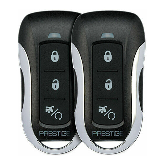
Detailed Descriptions: System Operation Remote Control Operation This system includes two (2) remote controls. The matrix below describes the basic functions of each remote. See Owners Guide for complete remote operation matrix. Three Button Remotes (1-Way) Button Action Function Press 1x Lock Hold 3 Seconds Panic ON/OFF... -
Page 15: Quick Reference
Quick Reference: System Programming Programming Mode Entry and Exit Procedure Once the system is installed and powered up, you will use the vehicle ignition, override button and a programmed remote control to set all system options. Feature options are divided into categories, or Banks, as described throughout this section. -
Page 16: Feature Bank Options
Quick Reference: System Programming Bank 1: Transmitter Programming Options See page 7 for a detailed description. Feature Bank 1 Descrip�on 1 Auto Program/Lock Press Lock bu�on on remote 2 Unlock Press Unlock bu�on on remote 3 Trunk/Start Press Start bu�on on remote Bank 2: Keyless Options See pages 8-9 for detailed descriptions. -
Page 17: Tach Function
Quick Reference: System Programming & Diagnostics Data Port Protocol Selection The default data port protocol of this model is ADS (iDatalink 2-Way). This model is capable of detecting the correct data port protocol (ADS or DBI) and automatically configuring Feature Bank 2; Feature 18. To initialize the detection procedure: 1. -
Page 18: Silent Lock And Unlock
The LED will flash one (1) time for ON, two (2) times for OFF. This feature will not affect LED flash during programming. Troubleshooting Remote Start All Prestige remote start system will provide parking light feedback to display remote start errors or shutdowns. The vehicle parking lights will flash to display error or shutdown code. -
Page 19: Door Lock Connections
Quick Reference: Wiring Diagrams Door Lock Connections Negative-Trigger Door Locks Verification: The vehicle wires register Ground when the Lock and Unlock switches are activated. RED ( - ) Lock Output Lock Vehicle Door Lock Control Relays Unlock GREEN ( - ) Unlock Output Positive-Trigger Door Locks Verification: The vehicle wires register 12V+ when the Lock and Unlock switches are activated. - Page 20 Quick Reference: Wiring Diagrams Door Lock Connections Single-Wire Negative Multiplex Door Locks (Relays required) Verification: The vehicle wire registers variable Ground values when the Lock and Unlock switches are activated. Please consult the vehicle-specific wire and location chart for resistor values. Ground Fused +12 Volt RED ( - ) Lock Output...
- Page 21 Quick Reference: Wiring Diagrams Door Lock Connections Reverse-Polarity Door Locks (Relays required) Verification: The vehicle wires rest at Ground and register 12V+ when the Lock and Unlock switches are activated. Fused +12 Volt Battery Souce RED ( - ) Lock Output Lock To Door Lock Motor Unlock...
- Page 22 Quick Reference: Wiring Diagrams VOXX APS57TM_RevA_07/20...
Need help?
Do you have a question about the APS57TM and is the answer not in the manual?
Questions and answers