Table of Contents
Advertisement
Available languages
Available languages
Quick Links
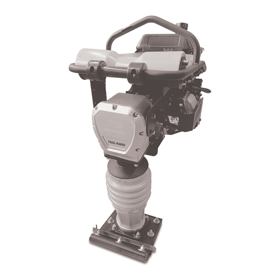
TMG-RM80
PRODUCT MANUAL
v.2022.10.13
VIBRATORY RAMMER
JUMPING JACK
WARNING
• Please read and understand the product manual completely before assembly
• Check against the parts list to make sure all parts are received
• Wear proper safety goggles or other protective gears while in assembly
• Do not return the product to dealer. They are not equipped to handle your requests.
Missing parts or have questions on assembly?
Please call: 1-877-761-2819 or email: cs@tmgindustrial.com
TOLL FREE: 1-877-761-2819
www.tmgindustrial.com
Advertisement
Chapters
Table of Contents
Troubleshooting

Subscribe to Our Youtube Channel
Related Manuals for TMG TMG-RM80


Summary of Contents for TMG TMG-RM80
- Page 1 TMG-RM80 PRODUCT MANUAL v.2022.10.13 VIBRATORY RAMMER JUMPING JACK WARNING • Please read and understand the product manual completely before assembly • Check against the parts list to make sure all parts are received • Wear proper safety goggles or other protective gears while in assembly •...
-
Page 2: Table Of Contents
CONTENT Ⅰ. INTRODUCTION........................- 2 - Ⅱ.SAFETY&ALERT SYMBOLS....................- 2 - 2.1 SAFETY SYMBOLS......................- 3 - 2.2 HAZARDS SYMBOLS..................... - 3 - 2.3 GENERAL SAFETY......................- 5 - 2.4 TRANSPORTING......................- 7 - 2.5 MAINTENANCE.......................- 7 - 2.6 EMERGENCIES....................... - 7 - Ⅲ. -
Page 3: Ⅰ. Introduction
Ⅰ. INTRODUCTION Thank you for your selection of our equipment. We have taken care in the design, manufacture and testing of this product. Should service or spare parts be required, prompt and efficient service is available from our branches. Ge ne ral Safe ty instructions for the Ope ration of Powe r Equipme nt. Our factory’s goal is to produce power equipment that helps the operator work safely and efficiently. -
Page 4: Safety Symbols
2.1 SAFETY SYMBOLS The thre e (3) Safe ty Me ssage s shown be low will inform you about pote ntial hazards that could injure you or others. The three Safety Messages specifically address the level of exposure to the operator, and are preceded by one of three words: DANGER, WARNING and CAUTION. - Page 5 WARNING Respiratory Hazards ALWAYS wear approved respiratory protection when required. CAUTION Rotating Parts Hazards NEVER ope rate e quipme nt with cove rs, or guards re move d. Ke e p fingers, hands, hair and clothing away from all moving parts to prevent injury. CAUTION Accidental Starting Hazards ALWAYS place the ON/OFF switch in the OFF position when the rammer is not in use.
-
Page 6: General Safety
DANGER Read this manual Failure to follow instructions in this manual may le ad to se rious injury or e ve n de ath! This e quipme nt is to be ope rate d by traine d and qualifie d pe rsonne l only! This e quipme nt is for industrial use only. - Page 7 High Temperatures – Allow the engine to cool before adding fuel or performing service and maintenance functions. Contact with hot components can cause serious burns. The e ngine se ction of this ramme r re quire s an ade quate fre e flow of cooling air. NEVER ...
-
Page 8: Transporting
2.4 TRANSPORTING ALWAYS shut down engine before transporting. Tighten fuel tank cap securely and close fuel cock to prevent fuel from spilling. Drain fuel when transporting rammer over long distances or bad roads. When placing the rammer inside a truck-bed for transport, always tie-down the rammer. ... -
Page 9: Ⅲ. General Information
Ⅲ. GENERAL INFORMATION 3.1 DEFINITION The tamping rammer is a powerful compacting tool capable of applying a tremendous force in conse cutive impacts to a soil surface . Its applications include soil compacting for road, e mbankme nts and re se rvoirs as we ll as backfilling for gas pipe line s, wate r pipe line s and cable installation work. - Page 10 Fig 1 shows the location of the controls and components for the tamping rammer. The function of each control is described below: Throttle Lever – Controls engine speed and the tamping action of the rammer. Engine Stop Switch –Controls the starting and stopping of the engine. Switch must be in the “ON” position when starting the engine.
-
Page 11: Basic Engine
3.4 BASIC ENGINE Fig 1A The e ngine (Fig 1A) must be che cke d for prope r lubrication and fille d with fue l prior to operation. Refer to the Engine User’s Manual for instructions. Se condary Air Cle ane r – Pre ve nts dirt and othe r de bris from e nte ring the fue l system. Remove wing-nut on top of air filter canister to gain access to filter element. -
Page 12: Ⅳ. Operation
Ⅳ. OPERATION This section is intended to assist the operator with the initial start-up of the Tamping Rammer. It’s extremely important that this section should be read carefully before attempting to operate the rammer. DO NOT use your rammer until this section is thoroughly understood. CAUTION Read Manual Failure to understand the operation of the Tamping Rammer could result in severe damage to the... -
Page 13: Check Engine
4.2 CHECK ENGINE Fill the fuel tank (Fig 3) with unleaded gasoline. At the same time, check the engine oil and make it a habit to replenish it often. Fig 3 Fig 4 Low le ve ls of oil may re sult in e ngine se izure due to high le ve ls of consumption during operations. -
Page 14: Start
4.4 START Open the fuel shut-off valve by moving the fuel cock lever to the OPEN position (Fig 5) then set the engine start/stop switch (Fig 5) to the START position. Fig 5 Set the engine ON/OFF switch (Fig 6) to the ON position (start). Fig 6 Close the choke lever (Fig 7) and move the throttle lever to the Full Open position. - Page 15 Fig 8 If e ngine fails to start, move the choke le ve r (Fig 7) to the half ope n position to avoid flooding. Repeat steps 1 to 4. If the e ngine doe s not start afte r re pe ate d atte mpts, che ck the spark plug for e xce ss fuel. Clean and replace the spark plug as needed.
-
Page 16: Stop Engine
The Tamping ramme r is de signe d to run at 4.000 rpm. At optimum rpm the foot hits at the rate of 680 impacts pe r minute . Incre asing throttle spe e d past factory se t rpm doe s not incre ase impacts and may damage unit. -
Page 17: Ⅴ.maintenance
Ⅴ.MAINTENANCE DAILY Thoroughly re move dirt and oil from the e ngine and control are a. Cle an or re place the air cle ane r e le me nts as ne ce ssary. Che ck and re tighte n all faste ne rs as ne ce ssary. Che ck the spring box and bellows for oil leaks. - Page 18 Figure 12 Engine Air Cleaner 200 – 300 HOURS (Oil Bath) Drain oil reservoir on foot housing (Figure 13). Refill with approximate ly 1.7 pt. (800cc) of 10W-30 motor oil. Oil should be midway in sight glass. Break in oil should be changed after first 50 hours.
-
Page 19: Ⅵ. Troubleshooting
Ⅵ. TROUBLESHOOTING 6.1 ENGINE TROUBLESHOOTING SYMPTOM POSSIBLE PROBLEM SOLUTION Difficult to start Fuel is available but Ignition plug being bridge? Check ignition system. spark plug will not Carbon deposit at ignition? Clean or replace ignition. ignite. (Power Short circuit due to defective available at high Replace insulators. -
Page 20: Rammer Troubleshooting
SYMPTOM POSSIBLE PROBLEM SOLUTION Governor adjustment Adjust governor to correct lever. improper? Rotational speed Governor spring defective? Clean or replace ignition. fluctuates. Fuel flow erratic? Check fuel line. Air take n in through suction Check suction line. line? Recoil starter not Dust in rotating part? Clean recoil starter assembly. -
Page 21: Ⅶ. Replacement Parts List
Ⅶ. REPLACEMENT PARTS LIST 7.1 GUIDE CYLINDER AND FOOT ASSY 20/50 TOLL FREE: 1-877-761-2819 www.tmgindustrial.com... - Page 22 PART NO. DESCRIPTION Sunk Head Bolt 12*70H Sunk Head Bolt 12*55 H Metal Sheet Foot Foot Assy Washer φ12 Washer φ12 Nylon Nut M12 Nut M18 Socket Head Bolt 10*20T Socket Head Bolt 10*35T Foot Plate Packing 1/4(CU) Plug M12*1.25 O-ring G-90 Inner Spring Out Spring...
-
Page 23: Crankcase And Engine Assy
7.2 CRANKCASE AND ENGINE ASSY 22/50 TOLL FREE: 1-877-761-2819 www.tmgindustrial.com... - Page 24 PART NO. DESCRIPTION Bolt 6*18H Case Cover O-ring 22.4*2.65 Hexagonal Bolt 8*20 Washer M8 Internal Circlip φ50 Bearing6204 Connecting rod Gear wheel Internal circlip φ62 Bearing 6207 Bearing 6305-2Z Crank Case External Circlip φ20 O-ring 40*2.4 Bearing Cover Key 5*20 Pinion Bearing 6204 Bearing 6007...
-
Page 25: Tank And Handle Assy
7.3 TANK AND HANDLE ASSY 24/50 TOLL FREE: 1-877-761-2819 www.tmgindustrial.com... - Page 26 PART NO. DESCRIPTION Handle Cover Shock Absorber Shock Absorber Holder (right) Shock Absorber Holder (left) Fuel Tank Throttle Lever Roller Handle Bolt M10*30 Washer Φ10 Spring Washer Φ10 Bolt M6*18 Fuel Tank Cap Socket Head Bolt M6*50 Washer Φ6 Spring Washer Φ6 Nut M6 Socket Head Bolt M6*30...
- Page 27 SOMMAIRE I. INTRODUCTION……………………………………………………............…………………………………….. II. SYMBOLS DE SÉCURITE ET D’ALERTE……………………………………..........……………………….. 2.1 SYMBOLS DE SÉCURITÉ…………………………………………..........……………..………………….. 2.2 SYMBOLS DE RISQUE………………………………………….............…………………………………... 2.3 SECUTITE GÉNÉRALE………………………………………….............………………………………….. 2.4 TRANSPORT…………………………………………………………………............……………………… 2.5 MAINTENANCE……………………………………………………………............………………………… 2.6 URGENCES……………………………………………………………………............…………………….. III. RENSEIGNEMENTSGÉNÉRAUX………………………………..…………………………..........…………..3.1 DÉFINITION…………………………………………………………………………............….………….. 3.2 CONSTRUCTION…………………………………………………………………………............…………. 3.3 CONTROLS………………………………………………………………………............…………………... 3.4 MOTEUR DE BASE……………………………………………………………............……………………. IV. OPÉRATION………………………………………………………………………………………............………... 4.1 VÉRIFIER LE BAIN D'HUILE DE CYLINDRE DERESSORT……....………......………………………...
-
Page 28: Introduction
I. INTRODUCTION Merci de votre sélection de notre équipement. Nous avons pris soin de la conception, de la fabrication et de l'essai de ce produit. Le service ou les pièces détachées doivent-ils être requis, un service rapide et efficace est disponible auprès de nos succursales. Le sconsigne s générale s de sécurité... -
Page 29: Symbols De Sécurité
2.1 SYMBOLS DE SÉCURITÉ Le s trois (3) me ssage s de sécurité ci-de ssous vous informe ront de s risque s pote ntie ls qui pourraie nt vous ble sse r ou d'autre s pe rsonne s. Les trois me ssage s de sécurité traite nt spécifique me nt du niveau d'exposition à l'opérateur et sont précédés d'un des trois mots: RISQUE, AVERTISSEMENT et ATTENTION. - Page 30 AVESTISSEMENT Risques respiratoires TOUJOURS porter une protection respiratoire approuvée si nécessaire. ATTENTION isques de pièces tournantes NE JAMAISutilise r l'équipe me nt avec de s couvertures ou des dispositifs de prote ction retirés. Gardez le s doigts, le s mains, le s che ve ux e t le s vête me nts à l'écart de toute s le s pièce s en mouvement pour éviter les blessures ATTENTION Risques du démarrage accidentels...
-
Page 31: Secutite Générale
RISQUE Lire ce manuel Le non-re spe ct des instructions contenues dans ce manue l pe ut e ntraîne r des ble ssure s grave s ou même la mort! Ce t équipe me nt doit être utilisé par un pe rsonne l formé e t qualifié unique me nt! Ce t équipe me nt est exclusivement pour usage industriel. - Page 32 Le fabricant n'assume aucune re sponsabilité pour tout accide nt e n raison de s modifications apportée s à l'équipement. NE JAMAIS utilise r de s acce ssoire s ou de pièce s jointe s, ce qui n'e st pas re commandé pour cet équipement. ...
-
Page 33: Transport
La prudence doit être exercée lors de l'entretien de cet équipement. Garder toutes les personnes inexpérimentées et non autorisées loin du matériel en tout temps. Les modifications non autorisées du matériel annuleront toutes les garanties. NE JAMAIS verser ou pulvériser de l'eau sur le moteur. Testez l'interrupteur ON / OFF du moteur avant de l'utiliser. -
Page 34: Renseignementsgénéraux
III.RENSEIGNEMENTS GÉNÉRAUX 3.1 DEFINITION Le pilon compacte ur e st un outil de compactage puissant capable d'applique r une énorme force dans les impacts consécutifs à la surface du sol.Ses applications incluent le compactage du sol pour la circulation routière, le s re mblais e t le s rése rvoirs, ainsi que le re mblayage de s gazoducs, de s conduite s d'e au e t de s travaux d'installation du câble. - Page 35 La figure 1 montre l'emplacement des commandes et des composants pour le propulseur du compacteur. La fonction de chaque commande est décrite ci-dessous: Le vie r d'accélérate ur - Pe rme t de contrôle r le régime du mote ur e t l'action de compactage du compacteur. Interrupteur d'arrêt du moteur - Contrôle le démarrage et l'arrêt du moteur.
-
Page 36: Moteur De Base
3.4 MOTEUR DE BASE Le mote ur (Fig 1A) doit être vérifié pour une lubrification appropriée e t re mpli de carburant avant son fonctionnement. Reportez-vous au mode d’emploi du moteur pour obtenir des instructions. Filtre à air secondaire–empêche la saleté et d'autres débris d'entrer dans le système d'alimentation. Le vie r d'étrangle ur–Utilisé... -
Page 37: Opération
IV.OPERATION Cette section est destinée à aider l'opérateur avec le démarrage initial du pilon compacteur.Il est e xtrême me nt important que ce tte se ction soit lue atte ntive me nt avant d'e ssaye r de faire fonctionne r le compacteur. N’utilisezPAS votre compacteur jusqu'à... -
Page 38: Vérifier Le Moteur
4.2 VÉRIFIER LE MOTEUR Remplir le réservoir d'essence (Fig. 3) avec de l'essence sans plomb. Dans le même temps, vérifier l'huile à moteur et faire l'habitude de la reconstituer souvent. Réservoir d’essence Jauge de niveau d'huile Le s faible s nive aux d'huile pe uve nt e ntraîne r une crise du mote ur e n raison de s nive aux éle vés de consommation pendant les opérations. -
Page 39: Démarrage
4.4 DÉMARRAGE Ouvrir le robine t d'arrêt du carburant e n déplaçant le le vie r du robine t de carburant e n position OUVERTE (Fig. 5), puis régle z le commutate ur de démarrage / arrêt du mote ur (Fig. 5) e n position START. Robinet de carburant filtre à... - Page 40 Démarreur de recul Si le moteur ne parvient pas à démarrer, déplacer le levier du démarreur (Fig. 7) jusqu'à la demi-position ouverte pour éviter les inondations. Répéter les étapes 1 à 4. Si le mote ur ne démarre pas après de s e ssais répétés, vérifie r la bougie d'allumage pour l’e xcès de carburant. Nettoyer et remplacer la bougie d'allumage au besoin.
-
Page 41: Arrêt Du Moteur
Le Pilon Compacteur est conçu pour fonctionner à 4.000 tr / min.Au rpm optimal, le pied atteint le taux de 680 impacts par minute. L'augmentation de la vitesse d'accélération dépassant les rpm définis en usine n'augmente pas les impacts et peut endommager l'unité. Le compacteur est conçu pour avancer lors du compactage. Pour une avance plus rapide, tirer légèrement sur la poignée de sorte que l'arrière du pied entre en contact d'abord avec le sol. -
Page 42: Maintenance
V. MAINTENANCE QUOTIDIEN Re tire r complète me nt la sale té e t l'huile du mote ur e t de la zone de contrôle . Ne ttoye r ou re mplace r les éléments du filtre à air si nécessaire. Vérifier et resserrer toutes les attaches si nécessaires. Vérifier la boîte à ressort et le soufflet pour les fuites d'huile. - Page 43 Filtre à air Figure12 Filtre à Air du Moteur 200–300 HEURES (Bain d’Huile) Vidange r le rése rvoir d'huile sur le boîtie r du pie d(Figure 13).Re charge r e nviron 1,7 pt. (800 cc) d'huile à mote ur 10W-30. ...
-
Page 44: Dépannage
VI. D ÉPANNAGE 6.1 DÉPANNAGE DU MOTEUR SYMPTÔME PROBLÈME POSSIBLE SOLUTION Difficile à démarrer La fiche d'allumage est-elle un pont? Vérifiez le système d'allumage. Dépôt de carbone à l'allumage? Nettoyer ou remplacer l'allumage. carburant e st disponibl e , mais la Court circuit e n raison de défectueux bougie... -
Page 45: Dépannage Du Compacteur
SYMPTÔME PROBLÈME POSSIBLE SOLUTION réglag e gouv e rn e ur est-il Réglerle régulateur pour corriger le levier. inapproprié? Le gouverneur est-il défectueux? Nettoyer ou remplacer l'allumage. La vitesse de rotation fluctue. Le flux de carburant est-il erratique? Vérifier la ligne de carburant. Air rentré... -
Page 46: Liste De Pièces De Rechange
VII. L ISTE DE PIÈCES DE RECHANGE 7.1 ASSEMBLAGE DU GUIDE DE CYLINDRE ET DU PIED 45/50 TOLL FREE: 1-877-761-2819 www.tmgindustrial.com... - Page 47 NO. PARTIE DESCRIPTION QTé Boulon à tête brisée 12*70H Boulon à tête brisée12*55H Tôle en feuille Pied Assemblage du pied Washerφ12 Rondelleφ12 Écrou de nylonM12 ÉcrouM18 Boulon à tête creuse10*20T Boulon à tête creuse 10*35T Plaque de pied Emballage1/4(CU) Bouchon M12*1.25 Joint toriqueG-90 Ressort intérieur Ressort extérieur...
-
Page 48: Assemblagedu Carter Et Du Moteur
7.2 ASSEMBLAGE DU CARTER ET DU MOTEUR 47/50 TOLL FREE: 1-877-761-2819 www.tmgindustrial.com... - Page 49 NO. PARTIE DESCRIPTION QTé Boulon6*18H Capot du châssis Joint torique22.4*2.65 Boulon Hexagonal8*20 RondelleM8 Circlips intérieurφ50 Palier 6204 Bielle Engrenage Circlips intérieurφ62 Palier6207 Palier6305-2Z Cartet Circlipextérieurφ20 Joint torique40*2.4 Couvercle de palier Clé5*20 Pignon Palier6204 Palier6007 Joint d'huile40*68*8 Tambour d'embrayage Rondelle¢8*7 BoulonM8*25T Rondelleφ10 Boulon à...
-
Page 50: Assemblageducarteretdelapoignée
7.3 ASSEMBLAGEDUCARTERETDELAPOIGNÉE 49/50 TOLL FREE: 1-877-761-2819 www.tmgindustrial.com... - Page 51 NO. PARTIE DESCRIPTION QTé Poignée Couverture Amortisseur Spport d’amortisseur(droite) Spport d’amortisseur(gauche) Réservoir d'essence Levier d’accélérateur Poignée du rouleau BoulonM10*30 RondelleΦ10 Rondelle élastique Φ10 Boulon M6*18 Bouchon du réservoir d’essence Boulon à tête cr e us e M6*50 RondelleΦ6 Rondelle élastiqueΦ6 ÉcrouM6 Boulon à...
Need help?
Do you have a question about the TMG-RM80 and is the answer not in the manual?
Questions and answers