Table of Contents
Advertisement
Quick Links
TMG-ABC99
PRODUCT MANUAL
v2023.08.26
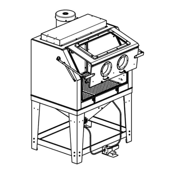
265 GALLON COMMERCIAL
CABINET SANDBLASTER
Please read and understand the product manual completely before assembly
Check against the parts list to make sure all parts are received
Wear proper safety goggles or other protective gears while in assembly
Do not return the product to dealer. They are not equipped to handle your requests.
Missing parts or questions on assembly?
Please call: 1-877-761-2819 or email: cs@tmgindustrial.com
Advertisement
Table of Contents

Subscribe to Our Youtube Channel
Related Manuals for TMG TMG-ABC99


Summary of Contents for TMG TMG-ABC99
- Page 1 TMG-ABC99 PRODUCT MANUAL v2023.08.26 265 GALLON COMMERCIAL CABINET SANDBLASTER Please read and understand the product manual completely before assembly Check against the parts list to make sure all parts are received Wear proper safety goggles or other protective gears while in assembly Do not return the product to dealer.
- Page 2 WARNING! This manual provides critical safety instructions on the proper setup, operation, maintenance, and service of this machine/tool. Save this document, refer to it often, and use it to instruct other operators. Failure to read, understand and follow the instructions in this manual may result in fire or serious personal injury—including amputation, electrocution, or death.
-
Page 3: Table Of Contents
TABLE OF CONTENTS INTRODUCTION....................................4 Manual Accuracy................................4 Machine Description.................................4 Identification..................................4 PRODUCTS SPECIFICATIONS................................5 SECTION 1:SAFETY.....................................6 Safety Instructions for Machinery.............................6 Additional Safety for Blast Cabinets..........................7 SECTION 2: POWER SUPPLY................................9 SECTION 3:SETUP....................................11 Needed for Setup................................11 Unpacking..................................11 Inventory..................................11 Site Considerations................................12 Mounting..................................13 Air System Setup................................14 Pneumatic Diagram................................15 Assembly..................................16 Test Run..................................20 SECTION 4: OPERATIONS.................................21... -
Page 4: Introduction
INTRODUCTION Manual Accuracy We are proud to provide a high-quality owner’s manual with your new machine! We made every effort to be exact with the instructions, specifications, drawings, and photographs in this manual. Sometimes we make mistakes, but our policy of continuous improvement also means that sometimes the machine you receive is slightly different than shown in the manual. -
Page 5: Products Specifications
PRODUCTS SPECIFICATIONS Product Dimensions: Weight .................................... 352 lbs. Width (side-to-side) x Depth (front-to-back) x Height ................51-1/2 x 47 x 69-1/2 in. Footprint (Length x Width) ........................... 24 x 47-1/2 in. Shipping Dimensions: Type................................... Wood Box Weight .................................... 451 lbs. Length x Width x Height ............................. -
Page 6: Section 1:Safety
SECTION 1: SAFETY For Your Own Safety, Read Instruction Manual Before Operating This Machine The purpose of safety symbols is to attract your attention to possible hazardous conditions. This manual uses a series of symbols and signal words intended to convey the level of importance of the safety messages. The progression of symbols is described below. -
Page 7: Additional Safety For Blast Cabinets
HEARING PROTECTION. Always wear hearing protection when operating or observing loud machinery. Extended exposure to this noise without hearing protection can cause permanent hearing loss. REMOVE ADJUSTING TOOLS. Tools left on machinery can become dangerous projectiles upon startup. Never leave chuck keys, wrenches, or any other tools on machine. - Page 8 MAINTAINING MACHINE. To prevent accidental contamination of shop air, check the blast cabinet for any leaks before use, and reseal immediately. AVOIDING ENTRAPMENT. To prevent an entrapment hazard for animals or children, always close and latch the blast cabinet door when not in use. LEAVING THE AREA.
-
Page 9: Section 2: Power Supply
SECTION 2: POWER SUPPLY Availability Before installing the machine, consider the availability and proximity WARNING of the required power supply circuit. If an existing circuit does not Electrocution, fire, hock, or meet the requirements for this machine, a new circuit must be installed. equipment damage may occur To minimize the risk of electrocution, fire, or equipment damage, if machine is not properly... - Page 10 Grounding & Plug Requirements This machine is equipped with a power cord that has an equipment WARNING -grounding wire and a grounding plug. Only insert plug into a matching Serious injury could occur if you connect machine to receptacle (outlet) that is properly installed and grounded in accordance power before completing setup process.
-
Page 11: Section 3:Setup
SECTION 3: SETUP Needed for Setup The following items are needed, but not included, for the setup/ WARNING assembly of this machine. This machine presents serious injury hazards to untrained users. Read Description through this entire manual to become familiar with the controls and Safety Goggles .............. -
Page 12: Site Considerations
Figure 2 Figure 3 NOTICE If you cannot find an item on this list, care- fully check around/inside the machine and packaging materials. Often, these items get lost in packaging materials while unpacking or they are preinstalled at the factory. Site Considerations Weight Load Refer to the Machine Data Sheet for the weight of your machine. -
Page 13: Mounting
Figure 4 Mounting Although not required, we recommend that you mount your new machine to the floor. Because this is an optional step and floor materials may vary, floor mounting hardware is not included. Generally, you can either bolt your machine to the floor or mount it on machine mounts. -
Page 14: Air System Setup
Air System Setup Air Supply The ability of this blast cabinet to accomplish its task is directly related to how well the air supply system is designed. For this blast cabinet to operate at its maximum potential for large blasting jobs, with the largest blast tip and widest spray pattern, the volume of compressed air feeding the regulator should be 35 CFM at 125 PSI. -
Page 15: Pneumatic Diagram
Pneumatic Diagram WARNING Disconnect the air supply before adjustments, maintenance, or service. Two-Stage Air Compressor Blast Cabinet Blast Gun Blast Cabinet Dedicated Media Blasting Air Regulator Air Dryer System Blast Cabinet Foot Valve... -
Page 16: Assembly
Assembly The machine must be fully assembled before it can be operated. Before WARNING beginning the assembly process, refer to Needed for Setup and gather all HEAVY LIFT! listed items. To ensure the assembly process goes smoothly, first clean Straining or crushing injury may any parts that are covered or coated in heavy-duty rust preventative occur from improperly lifting machine (if applicable). - Page 17 7. Fasten (4) stand legs and cross braces to hopper support, as Figure 11 shown in Figure 11, using (24) M8-1.25 x 20 hex bolts, (24) 8mm flat washers, (24) 8mm lock washers, and (16) M8-1.25 nuts. When mounting legs, only use (2) holes shown in Figure 11. CAUTION To eliminate pinch hazard, in next step, keep fingers clear of hopper support and blast cabinet mating surfaces.
- Page 18 14. Route blast gun hoses past notch in right table, and hang blast gun Figure 15 on its hook on right side of cabinet wall, as shown in Figure 15. Blast Gun and Hook 15. Fasten pressure gauge and regulator "L" bracket (see Figure 16) to left-front leg using (2) M6-1 x 12 cabinet screws and M6-1 flange nuts.
- Page 19 21. Using (4) M6-1 x 12 cabinet screws and M6-1 flange nuts, fasten Figure 19 dust collector to rear of cabinet so suction port protrudes through hole cut into back of cabinet (see Figure 19). 22. Remove inside-right baffle shown in Figure 20 from cabinet wall. Note: Removing this baffle provides access to full circumference of dust collector suction pipe so sealant can be evenly applied with- out leaks.
-
Page 20: Test Run
25. Install dust collector power cord in plastic raceway and snap cover Figure 22 in place, as shown in Figure 22. 26. Plug dust collector into power supply receptacle on rear of control box shown in Figure 23. 27. Pour desired amount of media into cabinet through front door. Cover DO NOT overfill. - Page 21 To test run machine: Figure 24 1. Clear all setup tools away from machine. 2. Make sure that DUST COLLECTOR ON/OFF rocker switch is in OFF position, as shown in Figure 24. 3. Connect machine to power source. 4 . Verify that dust collector and lights operate correctly by toggling LIGHT and DUST COLLECTOR switches to ON position.
-
Page 22: Section 4: Operations
If you are not experienced with this type of machine, WE STRONGLY RECOMMEND that you seek additional training outside of this manual. Read books/magazines or get formal training before beginning any projects. Regardless of the content in this section, TMG Industrial will not be held liable for accidents caused by lack of training. Preparation... - Page 23 4. Install correct tip into blast gun, in position shown in Figure 25. Figure 25 Typically, 6mm tip is used, but refer to Blasting Media section on Page 27 to understand when to use larger-sized tips. 5. Use canister plunger to tap filter clean and make sure canister is empty.
-
Page 24: Operation Tips
Operation Tips Improving Productivity Clean workpieces as much as possible by removing grease, oils, paint, rust, scale and other matter before beginning blasting operations (pressure washers can work well for this). Select the correct media for the task, and do not use air pressure settings that are too high for the media as it will cause media breakdown and dulling. -
Page 25: Blasting Media
Blasting Media Some of the common blasting media types are listed in this section with the MOH scale hardness value listed in parenthesis. All media have benefits and drawbacks, such as the quality of surface finish, media life, toxicity, and the precautions that must be taken to prevent environmental damage or personal injury to your respiratory system. - Page 26 —Coal Slag (6–7): This blast media is made from liquid coal slag that is collected from utility boilers. It then is hardened and crushed. The resulting media is sharp, angular, and fast-cutting with little dust. However, copper slag can release hazardous pollutants into the environment. Various grit sizes can be used from light blasting operations to heavy-duty rust, paint, and mill scale removal.
-
Page 27: Section 5: Maintenance
SECTION 5: MAINTENANCE WARNING Always disconnect power and air supply to machine before performing maintenance. Failure to do this may result in serious personal injury. Schedule For optimum performance from this machine, this maintenance schedule must be strictly followed. Ongoing To minimize your risk of injury and maintain proper machine operation, shutdown the machine immediately if you ever observe any of the items below, and fix the problem before continuing operations: •... -
Page 28: Section 6: Service
SECTION 6: SERVICE Review the troubleshooting and procedures in this section to fix or adjust your machine if a problem develops. If you need replacement parts or you are unsure of your repair skills, then feel free to call our Technical Support at 1-877-761-2819. Troubleshooting Operation Symptom... -
Page 29: Filter Replacement
Filter Replacement If, after a full filter cleaning, the cabinet still clouds up and general WARNING blasting visibility is poor, or if the dust collector has lost a Wear safety goggles and respirator when cleaning considerable amount of CFM, the filter must be replaced. cabinet or filter. - Page 30 4. While pulling fan cover upwards, use standard screwdriver to Fan Cover carefully pry out cover lock tangs just enough to clear hooks (see Figure 32), then remove cover from motor. Figure 32 Lock Tang Hook 5. Remove (2) screws that secure each brush housing and remove Figure 33 retainers (see Figure 33).
- Page 31 10. Finish cleaning process by using acetone and cotton rag to wipe off Figure 37 Spade Terminal any oils or contaminants from commutator. Inserts Here 11. Insert power wire spade terminal into brush assembly between brass sleeve and housing (see Figure 37). 12.
-
Page 32: Led Replacement
LED Replacement The three LED lights are accessed through the outside top of the cabinet (not from the inside of the cabinet). Items Needed LED Light Assembly (Part # P0714011V2-1)......1 Phillips Head Screwdriver #2 ..........1 Small Step Ladder ..............1 Safety Goggles ................. - Page 33 8. With help of assistant, place LED housing on top of cabinet, facing Figure 44 upwards, as shown in Figure 44. 9. Lift sheet of glass off cabinet, and set it on workbench for cleaning. 10. Disconnect any cords attached to LED you want to replace, and Figure 45 Cord remove LED (see Figure 45).
-
Page 34: Section 7: Wiring
SECTION 7: WIRING These pages are current at the time of printing. However, in the spirit of improvement, we may make changes to the electrical systems of future machines. Study this section carefully. If there are differences between your machine and what is shown in this section, call Technical Support at 1-877-761-2819 for assistance BEFORE making any changes to the wiring on your machine. -
Page 35: Wiring Diagram
Wiring Diagram DUST COLLECTOR ASSEMBLY Dust Collector Motor LED LIGHT ASSEMBLY LED 18W 36" LED 18W 36" LED 18W 36" Figure 49. Wiring component locations. SWITCH BOX DUST COLLECTOR FLUORESCENT LAMP ASSEMBLY SWITCH SWITCH (viewed from behind) (viewed from behind) 110 VAC 5-15 Plug (As Recommended) -
Page 36: Wiring Components
Wiring Components LED Light Assembly Dust Collector Motor Dust Collector Switch Box Assembly Assembly SECTION8: SAFETY LABELS... -
Page 37: Section9: Exploded View & Parts List
SECTION9: EXPLODED VIEW & PARTS LIST We do our best to stock replacement parts when possible, but we cannot guarantee that all parts shown are available for purchase. Call 1-877-761-2819 or visit www.tmgindustrial.com/parts to check for availability. Master Exploded View... -
Page 38: Master Parts List
Master Parts List PART NO. DESCRIPTION PART NO. DESCRIPTION Upper cabinet Assembled latches Round head cross screws M6x16 Welded cover board for falling sand (matched washers) Suction sand hose Pneumatic device of foot pedal Left grid Leg reinforces 1 Right grid Leg reinforces 2 Sealing tape Legs A... -
Page 39: Blast Cabinet Exploded View
Blast Cabinet Exploded View... -
Page 40: Blast Cabinet Parts List
Blast Cabinet Parts List PART NO. DESCRIPTION PART NO. DESCRIPTION Round head screws M6*32 Glove clamp Front window frame Inner glove ring Outer front window Outer glove ring Inner front window Glove set left and right Front window replacement film Hanger bracket Front window seal Front door... -
Page 41: Dust Collector Assembly Exploded View
Dust Collector Assembly Exploded View LED Light Assembly Exploded View... -
Page 42: Led Light Assembly Exploded View
LED Light Assembly Parts List PART NO. DESCRIPTION PART NO. DESCRIPTION LED Light 18W 36" LED 3-pin cable Light bracket Main LED cord 20G 3W 8" Rivet 4 x 10mm blind Electrical Box Assembly Exploded View Connecting line from LED Light Electrical Box Assembly Parts List PART NO.
Need help?
Do you have a question about the TMG-ABC99 and is the answer not in the manual?
Questions and answers