Table of Contents
Advertisement
Quick Links
PRODUCT MANUAL
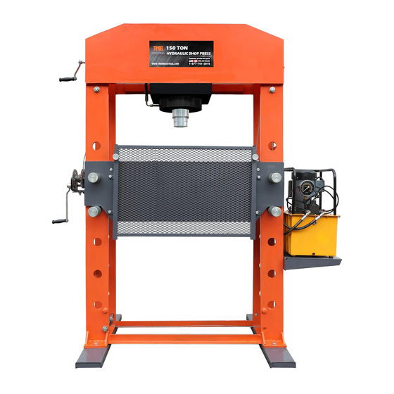
150 Ton Electric Hydraulic Shop Press
Model: TMG-SP150
m#S
0
Please read the product manual completely before assembly
Check against the parts list to make sure all parts are received
Wear proper safety goggles or other protective gears while in assembly
Missing parts or questions on assembly?
Please call: 1-877-761-2819 or email: cs@tmgindustrial.com
Do not return the product to dealer, they are not equipped to handle your requests
WWW.TMGINDUSTRIAL.COM
Toll Free:1-877-761-2819
Advertisement
Table of Contents

Subscribe to Our Youtube Channel
Related Manuals for TMG TMG-SP150


Summary of Contents for TMG TMG-SP150
- Page 1 PRODUCT MANUAL 150 Ton Electric Hydraulic Shop Press Model: TMG-SP150 Please read the product manual completely before assembly Check against the parts list to make sure all parts are received Wear proper safety goggles or other protective gears while in assembly Missing parts or questions on assembly? Please call: 1-877-761-2819 or email: cs@tmgindustrial.com...
-
Page 2: Intended Use
Typical applications include installation and removal of alternator and power steering pump bearings, axle bearings, transmission bearings, seals, u-joints and many other jobs. TECHNICAL SPECIFICATIONS Description Model: TMG-SP150 Capacity 150 Ton Working press(Ton) 150-165 Max. -
Page 3: General Safety Rules
GENERAL SAFETY RULES WARNING: Read and understand all instructions. Failure to follow all instructions listed below may result in serious injury. CAUTION: Do not allow persons to operate or assemble this Shop Press until they have read this manual and have developed a thorough understanding of how the Shop Press works. WARNING: The warnings, cautions, and instructions discussed in this instruction manual cannot cover all possible conditions or situations that could occur. -
Page 4: Safety Markings
DO NOT OPERATE OR REPAIR THIS EQUIPMENT WITHOUT READING THIS MANUAL. To maintain the Shop Press and user safety, the responsibility of the owner is to read and follow these instructions. Inspect the service shop press for proper operation and function. Keep instructions readily available for equipment operators. - Page 5 PLEASE READ THESE INSTRUCTIONS CAREFULLY. NOTE THE SAFETY INSTRUCTIONS AND WARNING. USE THE PRODUCT CORRECTLY AND WITH CARE FOR THE PURPOSE OF WHICH IT IS INTENDED. FAILURE TO DO SO MAY CAUSE DAMAGE TO PROPERTY AND/OR SERIOUS PERSONAL INJURY. PLEASE KEEP THIS INSTRUCTION MANUAL SAFE FOR FUTURE USE. We’ve done all we can to assure this press offers the utmost in safety, but you have to do your part.
- Page 6 ASSEMBLY All numbers in parenthesis ()refer to the index number from the parts breakdown. 1.Attach the two base support sections (46) to the base with bolt (45),washer (47)&(48)and nuts (49). 2.Attach the pallet (33) to the right frame with bolt (20).and washer (18) and (37) and (37)and nut(19). Attach the power unit(32) to the pallet with bolt (31).and washer (34) and (35) and nut(36).
- Page 7 Note:This hydraulic power unit is designed for vertical mount with reservoir feet down and reservoir breather up. Choose a flat mounting surface to bolt reservoir base to. CAUTION: The reservoir for this family of units is internally plumbed for vertical mounting as noted above.
- Page 8 5.Attach the handle winch (24) to the frame with bolt(20)and washer (18) and nut(19),Attach the handle (3) to the driving screw with bolt(1)and washer (2) 6. Raise the joined press bed frame (55) to the desired height and insert the bed frame pins (52) into the holes on the frames CAUTION: Press bed frame is heavy and could cause a potential hazard.
- Page 9 7.Verify that all bolts and screws have been tightened and The power line is grounded safely and firmly 8.When operating the equipment, be familiar with the operating gear of the reversing valve handle, so as to avoid misoperation and unnecessary accident risks. 9.The press is now ready for use.
-
Page 10: Power Unit
Power Unit AC motor Specifications: Pressure gauge High pressure 8500psi Low pressure 1450psi Control handle Tank Cap High flow 0.45GPM Low flow 2.10GPM Hydraulic Oil 32# anti wear hydraulic oil Tank Tank capacity 8Gallon AC motor 115V/60Hz, 2HP 1750RPM Totally enclosed fan cooled motors •... -
Page 11: Before Use
BEFORE USE 1.Before using this product, read the owner's manual completely and familiarize yourself thoroughly with the product and the hazards associated with its improper use. 2. Inspect before each use. Do not use if bent, broken or cracked components are noted. OPERATION All numbers in parenthesis()refer to the index number from the parts breakdown. -
Page 12: Prior To Operation
4. Align ram and work piece to ensure center-loading. Do not overload work piece. 5. Turn on the power, start the rotary switch (21), and operate the valve stem (30) to left as required to meet the dressing, disassembly or assembly requirements. Prior to operation: 1.Double check all hydraulic and electric connections. -
Page 13: Maintenance Instructions
MAINTENANCEINSTRUCTIONS If you use and maintain your equipment properly, it will give you many years of service. Follow the Maintenance instructions carefully to keep your equipment in good working condition. Never perform any Maintenance on the equipment while it is under a load. Inspection You should inspect the product for damage, wear, broken or missing parts(e.g.: pins) and that all Components function before each use. - Page 14 TO ADD OIL: The hydraulic cylinder assembly contains hydraulic fluid that must be kept at approximately 80% full at all times for proper operation. To check the oil level and to fill remove oil filler plug 1. Fully retract the hydraulic ram. 4.Screw the oil plug.
-
Page 15: Troubleshooting
TROUBLESHOOTING RAM WILL RAM WILL RAM WILL BLEEDS OFF POOR LIFT NOT EXTEND AFTER RETRACT CAUSES AND SOLUTIONS PRESS PERFORMANCE TO FULL PRESS AFTER LOAD EXTENSION OPERATION UNLOADING ✘ ✘ ✘ Release valve not tightly closed Ensure release valve tightly closed ✘... -
Page 16: Assembly Diagram
ASSEMBLY DIAGRAM WWW.TMGINDUSTRIAL.COM P16/19 Toll Free:1-877-761-2819... -
Page 17: Parts List
PARTS LIST Index# Part No. Qty. Index# Part No. Qty. Screw Screw M8X30 Big washer Valve handle Handle Power Unit Driving screw Bolt M8x25 Bolt-M 10x35 Install the plate Washer-10 Washer-8 Connecting plate Lock Washer-8 Bolt-M12x100 Nut-M 8 Ram fixup assembly Lock Washer-12 Outlet tube Bearing 61804... - Page 18 RAM ASSEMBLY DIAGRAM PARTS LIST Index# Part No. Description Qty. Screw M8X10 Piston Nuts Y-Ring-180x160x12 Wear ring Piston Head Screw M8X10 O-Ring-68x3.5 Piston Rod Pressure head Straight joint Cylinder nut Y-Ring-130x117x10 O-Ring-210x5.3 O-Ring-195x4 Cylinder Assembly Right-Angle Connect WWW.TMGINDUSTRIAL.COM P18/19 Toll Free:1-877-761-2819...
-
Page 19: Electric Circuit Diagram
ELECTRIC CIRCUIT DIAGRAM Motor:115V/60Hz 1Phase 2HP 1750RPM Power Switch Box AC motor WWW.TMGINDUSTRIAL.COM P19/19 Toll Free:1-877-761-2819...
Need help?
Do you have a question about the TMG-SP150 and is the answer not in the manual?
Questions and answers