
Related Manuals for Onicon Fox Thermal FT1


Summary of Contents for Onicon Fox Thermal FT1
- Page 1 Fox Thermal THERMAL MASS FLOW METER & TEMPERATURE TRANSMITTER Model FT1 www.foxthermal.com | 399 Reservation Road Marina, CA. 93933 106012 Rev. K...
- Page 2 Please note that Fox Thermal reserves the right to change and/or improve the product design and specification without notice. Fox Thermal FT1 Manuals: • Fox Thermal FT1 View™ Manual All Fox Thermal Manuals and software available in English only.
-
Page 3: Table Of Contents
Model FT1 Table Of Contents 1. Introduction Page 4 a. Quick Start Guide Page 4 b. Menu Trees Page 6 c. General Page 14 2. Installation (Mechanical) Page 17 a. Lateral Placement Page 18 b. Welding Branch Outlet to Pipe (Insertion) Page 20 c. -
Page 4: Quick Start Guide
Open the housing. If needed, the ACCESS DISPLAY BY UNSCREWING COVER orientation of display can be rotated in Precision Mass Flow Measurement An ONICON Brand 90° increments for a better view. REMOVE SCREWS ON DISPLAY TO ROTATE [refer to p. 23 for more information] DISPLAY ±180°... - Page 5 Model FT1 Quick Start Guide Before powering on your meter, use this worksheet to record your notes. Serial Serial Serial Serial Number: Number: Number: Number: Item to verify What is the Pipe ID? ID = ID = ID = ID = Calculate the Upstream/ UP = UP =...
-
Page 6: Menu Trees
Model FT1 Introduction: Menu Trees Fig. 1.1: FT1 Menu Tree - Main Menu Enter menu by scrolling to display 4 (p. 42) and entering the password (p. 50) MAIN MENU I/O FLO DSP EXIT Display Menu, p. 10 Flow Menu 1, p. 8 If RS485 hardware detected If HART hardware detected/with license If pulse/alarm hardware detected SET I/O SET I/O SET I/O COM 420 EXIT PUL 420 EXIT COM PUL 420 EXIT Communication Comm=HART mA=Flow None... - Page 7 Model FT1 Introduction: Menu Trees Fig. 1.2: FT1 Menu Tree - Digital Output MAIN MENU I/O FLO DSP EXIT Set I/O PUL 420 EXIT Not used OUT= Pulse Pulse NXT OK (p. 48) HiFloAlm LoFloAlm HiTempAlm LoTempAlm Pulse Alarm output SystemAlm Select 1 of 3 methods to scale (p. 54) the pulse output High Flow Alarm Pulse Output OUT= HiFloAlm P/U U/P FEQ EXIT NXT OK (p.
- Page 8 Model FT1 Introduction: Menu Trees Fig. 1.3: FT1 Menu Tree - Flow Menu 1 MAIN MENU I/O FLO DSP EXIT FLOW MENU 1 DGN UNT FM2 EXIT Flow Menu 2 Menu, p. 9 DIAGNOSTIC FLO UNT=SCFM (p. 58) SCFM (p. 51) SCFH SIM CAL‐V EXIT NXT OK NM3/H NM3/M KG/H KG/M KG/S TMP UNT=° F Deg F LBS/H Deg C...
- Page 9 Model FT1 Introduction: Menu Trees Fig. 1.4: FT1 Menu Tree - Flow Menu 2 MAIN MENU I/O FLO DSP EXIT FLOW MENU 1 DGN UNT FM2 EXIT FLOW MENU 2 GAS SPC PRM EXIT Parameters (p. 53) Level 2 (p. 56) Flow cutoff in selected units K fact = 0% Cutoff=12.5 SCFM CHG OK CHG OK ® Gas-SelectX Menu, p. 12 Pipe_id=4.026 In RESTORE DATABASE? Pipe id in inches or mm YES NO CHG OK Filter=0.8 Sec Flow Filter in seconds...
- Page 10 Model FT1 Introduction: Menu Trees Fig. 1.5: FT1 Menu Tree - Display Menu MAIN MENU I/O FLO DSP EXIT DISPLAY/PASSWORD DSP PSW EXIT Display 1 Line 1 (p. 48) (p. 50) FLo rate DSP1L1=FLo rate PASSWD=1234 Total NXT OK CHG OK Elps Display 1 Temp Line 2 Alarm FLo rate DSP1L2=Total Total NXT OK Elps Display 2 Temp Line 1 Alarm...
- Page 11 Model FT1 Introduction: Menu Trees Fig. 1.6: FT1 Menu Tree - CAL-V™ Menu MAIN MENU I/O FLO DSP EXIT FLOW MENU 1 DGN UNT FM2 EXIT DIAGNOSTIC MENU SIM CAL‐V EXIT (p. 60) CAL‐V MENU VER EXIT VERIFY CAL‐V? YES NO Hold value Flo: Hold value Go to zero NXT EXIT OK Take Control Off‐line EXIT OK Verifying CAL‐V Please Wait Verifying CAL‐V 0.512 T=123 Displays a CAL‐V value Displays the test’s during test count down timer CAL‐V=2.321 CAL‐V=0.259 CAL‐V=0.911 Fail OK...
- Page 12 Model FT1 Introduction: Menu Trees Fig. 1.7: FT1 Menu Tree - Gas-SelectX Menu ® MAIN MENU I/O FLO DSP EXIT FLOW MENU 1 DGN UNT FM2 EXIT FLOW MENU 2 GAS SPC PRM EXIT (p. 63) Methane GAS=Methane GAS=%Mix Select up to five gases for Gas NXT OK NXT OK Mix. Be sure mixture equals 100%. Nitrogen Helium Nat.Gas(mix) Methane = 65 % Argon UP DN OK Hydrogen CO2 = 30 % Propane UP DN OK Butane Oxygen Nitrogen = 5 % Ethane...
- Page 13 Model FT1 Introduction: Menu Trees Fig. 1.8: FT1 Menu Tree - Engineering Display Enter: Press F1 & F2 at the same time Press F4 to return to normal mode 3124.6 SCFM Flow rate measured by the meter Display 10 CSV = 0.3432 Volt Current Sense Voltage of sensor measurement circuit Pulse=1234.5 cnt Digital control counts of Pulse output Display 11 mA_420=234 cnt Digital control count of 4‐20mA output Elp=12.5 HR Elapsed time of meter operation Display 12 Stat(hex)=2800 Meter function and operation status code Alm=None Meter’s active alarms Display 13 FT1 V2.0 Firmware version of meter MB_Sn=P23949 Main board serial number Display 14 BB_Sn=P23945 Bridge board serial number MTR_Sn=123456 Meter serial number Display 15...
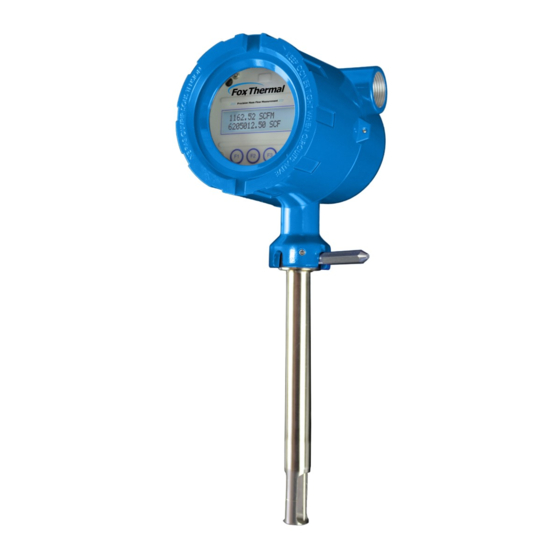
- Page 14 Model FT1 Introduction Welcome Thank you for purchasing the Model FT1 Thermal Gas Mass Flow Meter from Fox Thermal. The Model FT1 is one of the most technically advanced flow meters in the world. Extensive engineering effort has been invested to deliver advanced features, accurate measurement performance and outstanding reliability.
- Page 15 Model FT1 Introduction Calibration Validation Validate the calibration of the FT1 in the field using the CAL-V™ test. The goal of Calibration Validation is to provide operators with the ability to verify that the meter is capturing accurate data at scheduled recalibration times - or at any time - instead of sending the meter back to the factory for recalibration.
- Page 16 Model FT1 Introduction FT1 Functional Diagram An on-board 2 line x 16 character backlit LCD display shows flow rate, total flow, elapsed time, process gas temperature, and alarms. The display is also used in conjunction with the Configuration Panel for field configuration of flow meter settings such as 4-20mA scaling, frequency output scaling, pipe area, zero flow cutoff, flow filtering or dampening, display configurations, diagnostics, and alarm limits.
-
Page 17: General
Model FT1 Installation Installation Scope This section describes how to install the Fox Thermal Model FT1 Flow Meter and how to get started. Installation methods will vary according to the flow meter type (insertion or inline). For Insertion Types: 1. Determine lateral position on the pipe 2. -
Page 18: Lateral Placement
Model FT1 Installation Instructions for Flow Meter Lateral Placement Install the Model FT1 flow meter so that it is far enough away from bends in the pipe, obstructions, or changes in line sizes to ensure a consistent flow profile. See Fig. 2.1 below for your meter type (insertion/inline). - Page 19 Model FT1 Installation Tilt Installations - Moisture in the Gas or Condensation Tilt Installations - Moisture in the Gas or Condensation Tilted variations on installations help prevent moisture and condensation from forming Tilted variations on installations help prevent moisture and condensation from forming on the sensor and disrupting accurate flow measurement.
- Page 20 Model FT1 Installation Welding NPT Female Fitting to Pipe The probe of the FT1 must be installed perpendicular in the pipe to measure flow accurately. Use the following steps to ensure that the 1" NPT female fitting is correctly welded to the pipe. Directions: 1.
-
Page 21: Installation Depth
Model FT1 Installation Installation Depth The installation depth of the sensor in the pipe is dependent on the pipe size. To get the most accurate reading, proper placement of the sensor window within the pipe is necessary. As shown in Fig 2.2, the end of the sensor window should be 0.73" (18.5 mm) past the center line of the pipe. - Page 22 Model FT1 Installation Rotating the Enclosure The Model FT1 has been designed to allow the enclosure to rotate into four positions for optimal viewing of the display. To rotate the enclosure, first loosen the two set screws near the Flow Direction Indicator. Then unscrew and remove the Flow Direction Indicator to allow the enclosure to swivel into the desired position.
- Page 23 Model FT1 Installation Changing the Orientation of the FT1 Display The display can be rotated in 90° increments for optimal viewing of the display. First, open the enclosure by unscrewing the enclosure cap and loosen the two captive phillips screws to open the display assembly.
-
Page 24: Mounting Instructions
Model FT1 Installation Mounting Instructions - Compression Fittings The Model FT1 is mounted through a 0.781" (25/32") hole and a 1" female NPT branch outlet provided in the customer's pipe. Insertion style flow meters are not designed for use in pipes smaller than 1½". - Page 25 Model FT1 Installation Installation of a New Retractor Assembly NOTE! For instructions on how to properly weld the NPT female fitting onto pipe, please refer to Document #107590. 1. Remove collar clamp from probe using a 3/16" Hex Key. 2. Remove meter probe from retractor assembly and leave the ball valve open. 3.
- Page 26 Model FT1 Installation 4. Insert probe into retractor assembly and pipe to verify that the probe will fit through without obstructions. Carefully slide the probe through the retractor assembly and through the hole to see if there is interference by touching the pipe wall on the far side or until the probe cannot go deeper.
- Page 27 Model FT1 Installation 6. Using the equation (L + D/2 + 0.73") from Figure 2.8, calculate the insertion depth and mark on the probe while measuring from the end of the probe. 7. Ensure there is enough clearance to remove the meter from the retractor. See the Retractor Clearance table in Fig 2.8 for the model code of your meter.
- Page 28 Model FT1 Installation 8. Insert probe back into valve assembly to the depth mark and hand-tighten the compression fitting. 9. Verify that flow direction indicator is in line with pipe and in the direction of flow. Fig. 2.12: Flow Direction and Mounting Flow Direction Indicator Compression Nut &...
-
Page 29: Wiring (Electrical)
Model FT1 Wiring Wiring Instructions To wire the FT1 connect the power and signal wires to the terminal blocks according to the label and instructions on the following pages. Fig. 3.1: FT1 Wiring Access Loosen these two screws to open the display and access wiring terminals. -
Page 30: Signal Wiring
Model FT1 Wiring Wiring Precautions - WARNING! • Do not open the enclosure when energized or an explosive atmosphere is present. • Connect earth ground to a chassis ground screw on the inside or outside of FT1 enclosure to reduce the potential of an electrostatic charging hazard. •... - Page 31 Model FT1 Wiring: Input Power Power Input Requirements: 12 to 28VDC Supply External DC power supply must provide 12 to 28VDC (10 to 30VDC full input power range) at 6 Watts minimum. (With 12VDC power, the FT1 can use up to 500mA. With 24VDC power, the FT1 can use up to 250mA.) A 20 Watt or greater power supply is recommended to ensure it can provide enough current under all temperature, ventilation and power on conditions.
- Page 32 Model FT1 Wiring: Signal Wiring 4-20mA Output Wiring: Customer-Supplied Power Source Bring the 4-20mA wiring in through either conduit hub. Connect 4-20mA wiring as shown in the diagram below. Fig. 3.3: 4-20mA Output Wiring for Customer-Supplied Power Source Customer PLC or DCS +12 to 28VDC 4 to 20mA Flow Rate or Temperature 250 ohms typical with 24VDC Power...
- Page 33 Model FT1 Wiring: Signal Wiring 4-20mA Output Wiring: Loop Power Provided by FT1 Bring the 4-20mA wiring in through either conduit hub. Connect the 4-20mA as shown in the diagram below. Fig. 3.4: 4-20mA Output Wiring for Loop Power Provided by FT1 Customer PLC or DCS +12 to 28VDC 12 to 28VDC Return...
- Page 34 Model FT1 Wiring: Pulse/Alarm Wiring Pulse/Alarm Output Wiring: Customer Supplied Power Source (Recommended) Bring pulse/alarm wiring in through either conduit hub. Connect as shown in the diagram below. The pulse/alarm output is an open collector circuit capable of sinking a maximum of 20mA of current.
- Page 35 Model FT1 Model FT1 Wiring: Pulse/Alarm Wiring Pulse/Alarm Output Wiring: Power Provided by FT1 Bring pulse/alarm wiring in through either conduit hub. Connect as shown in the diagram below. The pulse/alarm output is an open collector circuit capable of sinking a maximum of 20mA of current.
- Page 36 Model FT1 Model FT1 Wiring: RS485 Modbus RTU or BACnet MS/TP RS485 Wiring for Modbus RTU or BACnet MS/TP Wiring connections are made as shown in the diagram below for Modbus communication. Termination Resistor Connect a termination resistor across the receive/transmit signals of the last device on the communication line.
- Page 37 Model FT1 Wiring: HART HART Wiring The HART connections are made as shown in the diagram below. NOTE! Meters ordered with HART will be configured for flow as default. If the customer changes the 4-20mA output to temperature, HART should report temperature. HART 4-20mA Output Wiring: Customer-Supplied Power Source The 4-20mA current loop and HART modem connections are made as shown in the diagram below.
- Page 38 Model FT1 Wiring: HART HART 4-20mA Output Wiring: Handheld Communicator The 4-20mA current loop connections are made as shown in the diagram below. A hand-held HART communicator can be connected to test points TP12 (+) and TP13 (-) with clip leads or to the 4-20mA terminal block. Fig.
- Page 39 Model FT1 Wiring: HART HART 4-20mA Output Wiring: Loop Power Provided by FT1 The 4-20mA current loop and HART modem connections are made as shown in the diagram below. Fig. 3.10: HART 4-20mA Output Wiring, Loop Power Provided by FT1 Customer PLC or DCS +12 to 28VDC 12 to 28VDC Return...
- Page 40 Model FT1 Model FT1 Operation: Start Up Start Up Sequence The program automatically enters the Run/Measure mode after power up. The screen will show the software version of the FT1 during power up. USB Interface The USB interface is a standard feature which allows communication with a PC to monitor readings and configure settings.
- Page 41 Model FT1 Model FT1 Operation: Display Screens Measurement Mode Display Screens In the measurement mode, there are four different display screens (display 1, 2, 3 and a prompt screen to enter the programming mode). Two display screens are user programmable (refer to Display Setup p.
-
Page 42: Programming
Model FT1 Operation: Programming Programming: Data Entry using the Display and Configuration Panel There are 2 basic types of menu entries: one for changing value or string and one for selecting from a selection list. To Change a Value or String : VALUE = 0.91234 Press CHG (F1) key to change the value, OK (F4) to accept the value. - Page 43 Model FT1 Operation: Programming Enter the correct password, then follow the instructions for changing a value as specified on page p. 42. The default Level 1 password is “1234”. If the wrong password is entered, the message “Wrong Password” will display and then return to the programming entry screen. Main Menu If the password is accepted, the Main Menu screen will be shown: MAIN MENU...
- Page 44 Model FT1 Operation: Programming screen will display: 4 mA = 0 SCFM Enter the value for the 4mA and press OK (F4). NOTE! When the flow rate exceeds the programmed value for the 20mA set point, the analog output will stay at 20mA and an alarm code will be generated. NOTE! 4mA is normally set to 0.
- Page 45 Model FT1 Operation: Programming NOTE! When the flow rate exceeds the programmed value for the 20mA set point, the analog output will stay at 20mA and an alarm code will be generated. Pulse/alarm Output If the Pulse/alarm feature was purchased as the second output for the Model FT1, it can be accessed from the Main Menu, press I/O (F1) (screen appearance may vary).
- Page 46 Model FT1 Operation: Programming Entering data in Pulse per Unit: From the Pulse/alarm Output Menu above, press P/U (F1) and the following screen will show: PLS/UNT = 2 Press CHG (F1) to change the setting and then OK (F4) to accept entry. The value entered is in pulse per selected flow unit total (i.e., 2 pulses per SCF).
- Page 47 Model FT1 Operation: Programming Alarm Output If the Pulse/alarm feature was purchased as the second output for the Model FT1, press I/O (F1) key from the Main Menu screen. The screen will show:. EXIT Then press PUL (F2) and the screen may show: OUT = HiFloAlm Then press NXT (F1) to select the correct alarm and press OK (F4).
- Page 48 Model FT1 Operation: Programming Serial Communication Settings If the RS485 Communication feature was purchased as the second output for the Model FT1, the Serial communication settings can be programmed by pressing I/O (F1) key from the Main Menu. The screen will show: SET I/O EXIT Press COM (F1) to select Serial communication.
- Page 49 Model FT1 Operation: Programming To Program Display Screens #1 & 2: From the Main Menu press DSP (F3) to select the Display Menu: DISPLAY/PASSWORD EXIT Press DSP (F1) key. The display will show: DSP1L1 = Flo rate These are the selections for the display #1 line #1. Selections are: Flo rate Flow rate...
- Page 50 Model FT1 Operation: Programming Password There are two user level passwords, only Level 1 is programmable and gives access to all the normal settings. The second password is used to allow access to calibration factors and should normally never be changed unless advised by the Fox Thermal service department, or to set a new password in the event that the user forgets the Level 1 password.
- Page 51 Model FT1 Operation: Programming To access the Unit Settings Menu: MAIN MENU EXIT Press FLO (F2): FLOW MENU 1 EXIT Press UNT (F2) for Unit selection. The screen will show: FLO = SCFM Press NXT (F1) to change selection and OK (F4) to accept. NOTE! The totalizer (total flow measured) will roll over when reaching a certain value.
- Page 52 Model FT1 Operation: Programming After pressing OK (F4) to accept the Flow unit the display will prompt for the temperature unit setting: TMP UNT= Deg F Press NXT (F1) to change selection and OK (F4) to accept. Selections for Temperature units are: Deg C Deg F After pressing OK (F4) to accept the temperature unit setting, the display will prompt for...
- Page 53 Model FT1 Operation: Programming PresRef= 14.7 Press CHG (F1) to change it and OK (F4) to accept. After the reference pressure is accepted, the FT1 will recalculate and display gas density at user's reference temperature and pressure: DNS = 1.2930 KG/m3 The gas density is for information only.
- Page 54 Model FT1 Operation: Programming Flow Cutoff Then press PRM (F3). The first parameter is Flow Cutoff: CUTOFF = 2.0 SCFM Enter the value for the low flow cutoff and then press OK (F4). When the flow rate falls below the zero flow cutoff, the flow meter will display a flow value of zero. Pipe Inside Diameter (ID) To set the Pipe Inside Diameter: Pipe_id = 3.068 In...
- Page 55 Model FT1 Operation: Programming This is the upper flow limit alarm value that can be associated with the alarm output. An alarm code is generated when the flow value exceeds this limit. If no checking is needed, this value should be set to zero. Press OK (F4) to accept the value.
- Page 56 Model FT1 Operation: Programming Press OK (F4) to accept the value. NOTE! If the programming menu was entered with a Level 2 password, then more menus will be shown concerning factory-set parameters that should not be changed. K Factor The K FACTOR allows the user to adjust the meter’s calibration. The Fox Thermal flow meter increases the calculated flow rate by the K Factor.
- Page 57 Model FT1 Operation: Programming that the meter was shipped with. All current user-entered settings will be overwritten. The green LP3 LED will flash at a faster pace until the recall is performed. The "RESET CRC" screen will follow "RESTORE DATABASE". Upon pressing OK (F4), an option to reset the NVRAM CRC will follow.
- Page 58 Model FT1 Operation: Programming Reset Total and Elapsed Time Enter the flow totalizer and elapsed time screen by pressing the F3 and F4 keys at the same time in the normal running mode (password required). RESET TOTAL ? Press YES (F4) to reset total and elapsed time. Press NO (F1) to cancel. NOTE! This feature is not available on non-resettable units.
- Page 59 Model FT1 Operation: Programming Pressing SIM (F1) will show: Simulate Flow? Press YES (F1) to continue. FloSim = 0 SCFM Enter the value and then press OK (F4). NOTE! Enter zero to disable this feature. Simulate Temp? Press YES (F1) to continue. TmpSim = 0 C Enter the value and then press OK (F4).
- Page 60 If the CAL-V™ test does not produce a "PASS" result, refer to "CAL-V™ Test Results" on page 62. NOTE! If the CAL-V™ test is performed using the Fox Thermal FT1 View™ Software, at the completion of the test, a CAL-V™ Certificate may be printed for a record of the test.
- Page 61 Model FT1 Operation: CAL-V™ Performing a CAL-V™ Test NOTE! • The FT1 will stop measuring flow when performing this test. Press FLO (F2) from the Main Menu. The display will show: FLOW MENU 1 EXIT Press DGN (F1). The display will show: DIAGNOSTIC CAL-V EXIT...
-
Page 62: Cal-V
Model FT1 Operation: CAL-V™ Process Stable? EXIT WARNING! If you are using a closed loop control, the system needs to be taken off-line during the test. Press OK (F4) to start CAL-V™. CAL-V™ test screen will show: Verifying CAL-V y.yyy T=xx This test takes about 3 minutes (200 seconds). - Page 63 Model FT1 Operation: Gas-SelectX ® Accessing the Gas-SelectX Gas Selection Menu Feature ® This menu allows the user to select a gas or gas mix from a pre-calibrated list of gases/gas mixtures available on the Fox Thermal Model FT1 Flow meter. Gases and gas mixes available in the Gas-SelectX feature include: ®...
- Page 64 Model FT1 Operation: Gas-SelectX ® To enter the programming mode from the normal monitoring mode and access the Gas- SelectX Menu, press the F1 or F2 key repeatedly until the following screen is shown: ® SET PARAMETERS? Press YES (F4) and the following screen will prompt the user to enter the password if it is active: PASWD:_ Enter the correct password and press OK (F4) to enter it.
- Page 65 Model FT1 Operation: Gas-SelectX ® Press GAS (F1) to access the Gas-SelectX feature. ® The display may show: GAS=Methane EXIT From this screen, the user will be able to access two aspects of the Gas-SelectX Menu: ® 1. Pure Gas = Choosing from a list of available gases, or 2.
- Page 66 Model FT1 Operation: Gas-SelectX ® GAS= %Mix The screen will show: Methane=0% This screen shows the percentage of the gas mixture allocated to methane. In this case, it shows 0%. To program the specific mixture of methane, press CHG (F1). Methane=30% To set the percentage of methane in the gas mix, press UP (F1) or DN (F2).
- Page 67 Model FT1 Operation: Gas-SelectX ® Once the desired gas percentages are programmed, press OK (F4). One of the following messages will appear: Gas Mix (100%) Shows only if no error is detected. Pressing OK allows exit to menu. Err: Mix=(110%) Shows only if gas mix does not equal 100%.
- Page 68 Modbus Introduction Scope This portion of the manual describes the Modbus implementation using RS485 serial communication physical layer for the Fox Thermal FT1 Mass flow meter based on the Modicon Modbus Protocol (PI-MBUS-300 Rev. J). Modbus Protocol Modbus Protocol is an application layer messaging protocol that provides client/sever communications between devices.
- Page 69 Model FT1 FT1 Commands Supported by Modbus Read Holding Registers (command 03) This command reads the basic variable from the FT1 and has the following format: Request: <Meter Address> <Command code=03> <Register start address high> <Register start address low> <Register count high> <Register count low> <CRC high> <CRC low> Response: <Meter Address>...
- Page 70 Model FT1 FT1 Commands Supported by Modbus Table 5.1: FT1 Modbus Holding Registers (cont'd) Modbus Data Type Description Units Register 40016 16-bit int Status 40017 16-bit int Status 2 40018 16-bit int Control Register (Write Only): Reset total =2 Perform_CAL_V = 173 Abort CAL-V = 174 40019 Reserved...
- Page 71 Model FT1 FT1 Commands Supported by Modbus Table 5.1: FT1 Modbus Holding Registers (cont'd) Modbus Data Type Description Units Register 40051 Reserved 40052 Reserved 40053 Reserved 40054 Reserved 40055 Reserved • Registers 40011, 40012, and 40013 are provided to get more resolution for low flow and total.
- Page 72 Model FT1 FT1 Commands Supported by Modbus Table 5.2: Status Bits Definitions for Command 04, Modbus Address 30001 Definition Comment Power up indication Cleared when out of the power up sequence Flow rate reached high limit threshold Set limit to zero to disable Flow rate reached low limit threshold Set limit to zero to disable Temperature reached high limit threshold...
- Page 73 Model FT1 FT1 Commands Supported by Modbus Preset Single Register (Command 06) This command writes a single register. This should not be used to write to register pairs because it may produce a corrupted setting. For instance, if you use two of these commands to write to a pair of registers that hold a floating point value, the value will be a combination of the old and new values after the first write and before the second.
- Page 74 Model FT1 Modbus Programming Communication Protocol and Parameters To program the communication parameters, start at the Main Menu: MAIN MENU EXIT Then press I/O (F1) to set Inputs/Outputs: SET I/O EXIT Then press COM (F1) to select communication parameters. Set Bus protocol for Modbus: Comm=Modbus Press NXT (F1) repeatedly until Modbus is selected as shown and then press OK (F4) to accept the setting.
- Page 75 Model FT1 Modbus Programming “19200” “9600” “4800” “2400” “1200” Parity=EVEN Press NXT (F1) repeatedly until the correct selection is shown and then press OK (F4) to accept the setting. Selections are: “NONE” “ODD” “EVEN” Address=02 Press CHG (F1) to change the address and then press OK (F4) to accept the setting. Selections are between 01 and 247.
- Page 76 Model FT1 Modbus Programming Table 5.4: Gas Selection Codes Selection Code Methane CO2 (Carbon Dioxide) Nitrogen Helium Argon Hydrogen Propane n-Butane Reserved Oxygen Ethane Iso Butane Pentane Hexane Heptane Octane Nonanes Mixed gas (must set percentages) Setting Mix Percentages When a custom mix type is selected, the percentages of each gas in the mix must be set. These percentages are 32-bit floating point numbers.
- Page 77 Model FT1 Modbus Programming 40070 32-bit float LSW Helium percentage Percent (31.4 = 31.4%) 40071 32-bit float MSW 40072 32-bit float LSW Oxygen percentage Percent (31.4 = 31.4%) 40073 32-bit float MSW 40074 32-bit float LSW n-Butane percentage Percent (31.4 = 31.4%) 40075 32-bit float MSW 40076...
- Page 78 This portion of the manual describes the BACnet MS/TP (RS485) implementation using RS485 serial communication physical layer for the Fox Thermal FT1 Mass flow meter. BACnet Protocol BACnet MS/TP (Building Automation and Control Network/Master Slave Token Passing) is a data link layer protocol designed for communication between devices in building automation control systems.
- Page 79 Model FT1 BACnet Protocol FT1 BIBB’s supported: DS-RP-B Read Property DS-WP-B Write Property DM-DDB-B Dynamic Device Binding DM-DOB-B Dynamic Object Binding DM-DCC-B Device Communication Control DS-RPM-B ReadPropertyMultiple DM-RD-B Reinitialize Device MS/TP baud rates: 9600, 19200, 38400, 57600, 76800, 115200 FT1 Character sets supported: ANSI X3.4, UTF-8 Fox Thermal BACnet vendor ID: 650 For more information about BACnet visit http://www.bacnet.org/.
- Page 80 Model FT1 BACnet Programming Communication Protocol and Parameters To program the communication parameters, press I/O (F1) key from the Main Menu. MAIN MENU EXIT This is the Main Menu for the programming mode. To exit the programming mode, press EXIT (F4) repeatedly until “Normal Mode” is seen briefly. Choose I/O (F1) to access the communication output.
- Page 81 Model FT1 BACnet Programming Next select the MS/TP Mac address. The selection is from 0-127. Please note that only one device can be on a MS/TP Mac address. MAC_ADD=23 Next select the MS/TP Max Master using CHG (F1). The selection is from 0-127. Press OK (F4) to accept the setting.
- Page 82 Model FT1 HART Introduction Scope The Fox Thermal Model FT1 transmitter complies with HART Protocol Revision 7.1. This section specifies all the device-specific features and documents HART Protocol implementation details (e.g., the Engineering Unit Codes supported). The functionality of this Field Device is described sufficiently to allow its proper application in a process and its complete support in HART- capable Host Applications.
- Page 83 Model FT1 HART Protocol Product Overview HART communication is transmitted over the FT1 4-20mA flow output signal and can be monitored and configured using a HART master device or a hand-held communicator. Process Flow Rate 4-20mA Analog Output The 4-20mA output of the FT1 HART represents the process flow rate measurement, linearized and scaled according to the configured range of the instrument.
- Page 84 Model FT1 HART Programming Status Information Device Status Bit 4 ("More Status Available") is set when any failure is detected. Command #48 provides additional detail. Extended Device Status This bit is set if a sensor error is detected. "Device Variable Alert" is set if the PV is out of limit. Additional Device Status (Command #48) Command #48 returns 2 Device-Specific Status bytes of data, with the following status information.
- Page 85 Model FT1 HART Programming Common-Practice Commands, Supported Commands The following common-practice commands are implemented: Write Damping Value Write Range Values Set PV Upper Range Values Set PV Lower Range Values Reset "Configuration Changed" Flag Enter/Exit Fixed Current Mode Write PV Units Trim Loop Minimum Trim Loop Maximum Read Additional Device Status (Command #48 returns 2 bytes of data)
- Page 86 Model FT1 HART Programming Capability Checklist Manufacturer, model Fox Thermal Instruments, FT1 Device type Transmitter HART revision Device Description available Number and type of sensors Number and type of actuators Number and type of host side 1 : 4-20mA analog signals Number of Device Variables Number of Dynamic Variables...
- Page 87 Model FT1 HART Programming Communication Protocol and Parameters To program the communication parameters, press I/O (F1) key from the Main Menu. MAIN MENU EXIT This is the Main Menu for the programming mode. To exit the programming mode, press EXIT (F4) repeatedly until “Normal Mode” is seen briefly. Choose I/O (F1) to access the communication output.
-
Page 88: Maintenance
Model FT1 Model FT1 Maintenance: Precautions PRECAUTIONS WARNING! BEFORE ATTEMPTING ANY MAINTENANCE, TAKE THE NECESSARY SAFETY PRECAUTIONS BEFORE REMOVING THE PROBE FROM THE DUCT (EXAMPLE: PURGE LINES OF TOXIC AND/OR EXPLOSIVE GAS, DEPRESSURIZE, ETC...). WARNING! EXPLOSION HAZARD. DO NOT REMOVE OR REPLACE COMPONENTS OR FUSES UNLESS POWER HAS BEEN DISCONNECTED WHEN A FLAMMABLE OR COMBUSTIBLE ATMOSPHERE IS PRESENT. - Page 89 Model FT1 Model FT1 Maintenance: General Broken or Damaged Probe If the sensor is broken or damaged, the probe and electronics must be returned to the factory for repair. A new sensor will be installed and calibrated. Refer to "Returning Your Meter" on p. 107.
- Page 90 Model FT1 Maintenance: Retractor Option Instructions for Removing and Inserting the Meter from a Pressurized Pipe using the Retractor WARNING! Possible injury or damage to equipment may occur if the retractor is not used correctly. Please read the following instructions carefully prior to using the retractor.
- Page 91 Model FT1 Maintenance: Retractor Option Step 2 - Remove the Probe from the Retractor Body 5. After removing the probe from the flow stream and closing the ball valve (#1-4 on previous page), slowly loosen the compression fitting (see figure 8.2), until the pressure in the retractor is relieved.
- Page 92 Model FT1 Maintenance: Retractor Option How to Insert the Probe into the Flow Stream (Valve closed, System Pressurized) 1. Carefully, slide the probe into the retractor. 2. Install the collar clamp just below the collar spacer, and tighten it in place on the probe. Slide the probe back out of the retractor until the cable is straight and taut.
- Page 93 Model FT1 Maintenance: Retractor Option 4. Verify that the probe is aligned with the centerline of the pipe, and pointed in the direction of flow. Figure 6.4 Flow Direction Indicator Compression Nut & Ferrules Compression Fitting 5. Secure the probe in place by tightening the compression nut with a 1 1/8" wrench and a 1 1/4"...
-
Page 94: Troubleshooting
Model FT1 Model FT1 Maintenance: Troubleshooting Troubleshooting CAUTION! The electronics and sensor supplied by Fox Thermal are calibrated as a single precision mass flow meter. Interchanging sensors will decrease the accuracy of the flow meter. If you experience any problem with your Model FT1 Flow meter, call Fox Thermal Customer Service Department, Technical Assistance at (831) 384-4300. - Page 95 Model FT1 Model FT1 Maintenance: Troubleshooting Problem Possible Cause Action Meter resets 1. Electromagnetic 1. Check meter power cycles value interference (EMI) 2. Press and release F1 and F2 at the 2. Low power supply same time; the display will enter voltage or intermittent Engineering screens.
- Page 96 Model FT1 Model FT1 Maintenance: Troubleshooting CAL-V™ Troubleshooting CAL-V™ If the FT1 Meter fails a CAL-V™ Calibration Validation test, there are a few reasons that could be the cause: 1. The sensor may be dirty or damaged • Visually inspect the meter and sensor for damage. If damage is found, meter may need to be serviced.
- Page 97 Model FT1 Model FT1 Maintenance: Troubleshooting Installation Problems Installation Problems The following is a summary listing of problems that may be encountered with the installation of the FT1 Thermal Mass Flow Meter. 1. Improper wiring connections for power and/or 4-20mA output signal. A separate power source is recommended for the FT1 main board and the 4-20mA output signals.
- Page 98 Model FT1 Alarm Codes Alarm Codes Information to diagnose and clear alarm codes is on p. 9 under the Menu Tree section. Enter password (9111) and follow the block diagram to get to the section affected by the error code. Alarm Reason Action...
-
Page 99: Appendices
Model FT1 Appendices: Specifications Performance Specs Flow Accuracy: Air: ±1% of reading ±0.2% of full scale Other gases: ±1.5% of reading ±0.5% of full scale Accuracy specification applies to customer's selected flow range Maximum range: 15 to 25,000 SFPM (0.07 to 118 NMPS) Minimum range: 15 to 500 SFPM (0.07 to 2.4 NMPS) Straight, unobstructed pipe requirement: Insertion meters: 15 diameters upstream;... -
Page 100: Specifications
Model FT1 Appendices: Specifications Operating Specs (cont'd) Gas Pressure (maximum): Insertion meter: 740 psig (51 barg) 316 SS inline meter with NPT ends: 500 psig (34 barg) 316 SS inline meter with 150 lb. flanges: 230 psig (16 barg) Carbon steel inline meter with NPT ends: 500 psig (34 barg) Carbon steel inline meter with 150 lb. -
Page 101: Agency Approvals
Model FT1 Appendices: Specifications Physical Specs Probe diameter: ¾" Sensor material: 316 stainless steel Enclosure: NEMA 4X, aluminum, dual ¾” FNPT conduit openings. Flow Meter Installation: Fox Thermal-supplied compression fitting connects to customer-sup- plied ¾” female branch outlet welded to pipe. Agency Approvals CE Mark: Approved EMC Directive;... - Page 102 Model FT1 Appendices: Dimensions Fig. 7.1 Insertion Meter Dimensions Measurements shown in inches (millimeters). Table 7.1 Insertion Meter with 316 stainless steel probe Probe Size Probe Size Dimension “LL” [model code] [inches] [inches / millimeters] 6" 6.0" (152 mm) 9" 9.0"...
- Page 103 Model FT1 Appendices: Dimensions Fig. 7.2 Insertion Meter with 150 psig Retractor Dimensions Measurements shown in inches (millimeters). (155.0) 4.64 (118.0) (61.0) 6.70 2X 3/4" NPT (160.0) (170.3) FEMALE RESTRAINT CABLE RESTRAINT CABLE MOUNT RETRACTOR WITH 1 INCH FULL PORT BALL VALVE 9.0±.3 "LL"...
-
Page 104: Dimensions
Model FT1 Appendices: Dimensions Fig. 7.3 Inline Meter with Flow Body and NPT End Connections - Dimensions Measurements shown in inches (millimeters). Table 7.3 Inline Meter with Flow Body and NPT End Connections Size Body Size Dimension “L” Dimension “H” [model code] [inches] [inches]... - Page 105 Model FT1 Appendices: Dimensions Fig. 7.4 Inline Meter with Flow Body and 150lb RF Flange End Connections - Dimensions Measurements shown in inches (millimeters). Table 7.4 Inline Meter with Flow Body and 150lb RF Flange End Connections - Dimensions Size Body Size Dimension “L”...
-
Page 106: Warranty
Model FT1 Appendices: Warranty Warranty (a) Fox Thermal (hereafter FOX) warrants that the products furnished under this Agreement will be free from defects in material and workmanship for a period of one year from the date of shipment. The customer shall provide notice of any defect to FOX, within one week after the Customer’s discovery of such defect. -
Page 107: Returning Your Meter
Model FT1 Appendices: Returning Your Meter Returning Your Meter The Fox Thermal Customer Service Department (PH: 831-384-4300 or FAX: 831-384-4312) can help you through the process of returning a meter for service. If it becomes necessary to return a Fox Thermal flow meter for service or recalibration, please follow these steps: 1. -
Page 108: Definitions
Model FT1 Definitions Glossary of Terms and Definitions American Wire Gauge Pulse per Unit Bara Bar absolute PIP A^2 Pipe Area Contact Programmable Logic Calibration Controller Change Parameters Communication Pressure Current Sense Voltage PSIA Pounds per Square Inch Direct Current Absolute Down Point... -
Page 109: Index
Model FT1 Index Index Access to Electronics, p. 21 Programming Alarm Codes, p. 98 Analog 4-20mA Output, p. 43 Alarm wiring, p. 34 Alarm Output, p. 47 Analog 4-20mA output, p. 43 Changing values or strings, p. 42 Breakage or Damage of Probe, p. 89 Display Setup, p. - Page 110 Wiring Definition of Terms Troubleshooting Tips NOTE! is used for Notes and Information WARNING! is used to indicate a hazardous situation which, if not avoided, could result in death or serious injury. CAUTION! is used to indicate a hazardous situation which, if not avoided, could result in minor or moderate injury.
Need help?
Do you have a question about the Fox Thermal FT1 and is the answer not in the manual?
Questions and answers