Table of Contents
Advertisement
Quick Links
Advertisement
Table of Contents

Related Manuals for Inovance AC700 Series


Summary of Contents for Inovance AC700 Series
-
Page 2: About This Manual
Preface About This Manual The AC700 series intelligent machine controller features outstanding motion control performance and diverse network interfaces to meet different expansion requirements. The controller can control equipment in a variety of industries, such as packaging, printing, die cutting, mobile phone manufacturing, silicon wafer manufacturing, logistics, and pharmacy. -
Page 3: Safety Precautions
Use this product in an environment that complies with the design specifications. Malfunction or ● component damage caused by improper usage is not covered by warranty. Inovance shall take no responsibility for any physical injuries or property loss caused by ● noncompliance with this guide or improper use of this product. - Page 4 Safety Precautions Use professional hoisting equipment operated by qualified professionals to move large-scale or ● heavy products. Failure to comply may result in physical injury or product damage. Before hoisting the product, confirm that the front cover, terminal block, and other parts of the ●...
- Page 5 Safety Precautions Cover the top of the product with cloth or paper during installation to prevent unwanted objects ● such as metal chippings, oil, and water from falling into the equipment and causing faults. After installation, remove the cloth or paper to prevent overtemperature caused by poor ventilation due to blocked ventilation holes.
- Page 6 Safety Precautions After wiring and parameter setting, perform a trial run to check whether the device can run ● properly. Failure to comply may result in physical injury or device damage. Before power-on, check that the rated voltage of the product is consistent with that of the power ●...
-
Page 7: Safety Signs
Safety Precautions Require repair services according to the product warranty agreement. ● When the fuse is blown or the circuit breaker or earth leakage current breaker (ELCB) trips, wait for ● at least the time specified on the product warning label before power-on or further operations. Failure to comply may result in equipment damage, physical injury, or even death. -
Page 8: Product Information
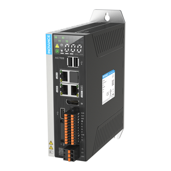
Product Information Product Information Nameplate and Model Number Nameplate Model number 1. Product Name 3. Serial No. (First Digit) 5. Operating System A: controller W: Windows 7: 7 series L: Linux 2. Structure Type 4. Hardware Configuration Code C: booksize type XX: two digits, which are defined based on functions and performance... - Page 9 Product Information Components 1.2.1 Appearance The AC700 series includes the following models: Type Description Model Serial No. AC702 01440300 Booksize controller Intel J1900; 4 GB memory; 64 GB hard drive; three USB 2.0 ports; three network ports; DP; with display; 16 axes...
- Page 10 Product Information Port Description Rear earhook Standard component Display Display For specific functions and operations, see “ 5.3 ” on page 37 3/11 USB port Three USB 2.0 ports LAN port Not supported LAN C port EtherCAT port Display Port (DP) I/O communication port Eight DIs/four DOs;...
-
Page 11: Product Specifications
Product Specifications Product Specifications Basic Specifications The AC700 series includes two controller models: AC702 and AC703. The following table provides basic specifications of the two models. Item AC702 AC703 Power supply 24 VDC (–15% to +20%) 24 VDC (–15% to +20%) -
Page 12: Environmental Specifications
3 axial directions 0 m to 2000 m Altitude/air pressure 0 m to 3000 m (> 70 kPa) EMC Specifications The following table provides EMC specifications of the AC700 series controller. Item Description Standard Conducted emission IEC61131-2:2017 Class A... - Page 13 Product Specifications Item Standard Description IEC61131-2:2017 Surge ±1 kV (line to ground) IEC 61000-4-5:2014+ Communication and signal ports A1:2017 Voltage dip: 40% U and 70% ; duration: 0.01s, 0.03s, 0.1s, 0.3s, 1s Voltage dip and short IEC 61000-4-29:2000 interruption Duration for short interruption: 0.001s, 0.003s, 0.01s、0.03s, 0.1s, 0.3s, 1s Power frequency magnetic field...
-
Page 14: Installation Requirements
Installation Installation Installation Requirements 3.1.1 Installation Precautions Observe the following precautions when installing the controller: Before installation, ensure that the controller is powered off. ● To avoid damage to the controller, do not drop or shock the controller's housing, terminal block, or ●... -
Page 15: Installation Instructions
Installation Installation Instructions 3.2.1 Installation Dimensions The following figure shows the installation dimensions of the controller. -
Page 16: Installation Method
Installation 3.2.2 Installation Method Install and secure the AC700 with three screws at the torque of 1.2 N m through the rear earhook and the bottom stand. Figure 3-1 Installing the controller through the rear earhook -15-... -
Page 17: Grounding Requirements
Wiring Wiring Cabling Suggestions 4.1.1 Grounding Requirements A grounding point ( ) is set on the power terminal of the controller and the rear earhook each. Choose one of the grounding points as needed, but the grounding point on the rear earhook is recommended. -
Page 18: Cabling Requirements
Wiring 4.1.2 Cabling Requirements Low-voltage cables (< 1 kV) are generally divided into four types. Only cables of the same type can be bundled together. Cables of different types must be separated without intersection or overlap. If intersection cannot be avoided, route cables in a right-angle crossover manner. Type Application Ethernet port and EtherCAT port... - Page 19 Wiring Wiring of the Power Input Port The power input terminal includes three pluggable pins spaced at 5.08 mm. You can use a spring to crimp the wire onto the terminal, thus facilitating wiring, replacement, and maintenance on site. The following figure shows how to insert the power cable connector into the power input port: Definition of the power input terminals Name...
- Page 20 Wiring Item Specifications Hold-up time 150 ms Foolproof Short circuit protection Note: The power input is equipped with a fuse. Power cable preparation requirements The power input cable uses a pin-type terminal. For preparation requirements, see “ 4.7.2 Cable Preparation Requirements ” on page 32 Wiring of the I/O Communication Port 4.3.1 Port Definition...
-
Page 21: Port Specifications
Wiring Definition of the I/O communication port Type Function Function Type Terminal I/O communication Terminal port RS485+ 485+ 232R RS232 receiving RS485– 485– 232T RS232 transmit- RS485 RS232 ting Serial port Serial port ground ground Power-on RUN/STOP signal High-speed High-speed input 0 input 1 High-speed... -
Page 22: Rs485 Communication Specifications
Wiring High-Speed digital output specifications (pins 19/20/21/22) Item Specifications Number of channels Output type DC digital output, transistor Output mode SINK Maximum output frequency 200 kHz (To reach 200 kHz, connect an external load equivalent to 12 mA or above.) 5 VDC to 24 VDC Voltage of the control circuit 5 mA... - Page 23 Wiring Internal structure Wiring of 8 high-speed DI and 4 high-speed DO terminals Wiring of the external circuit...
- Page 24 Wiring Internal structure 4.3.4 RS485 Bus Wiring Instructions Do not bundle the extension cable together with power cables (high voltage, large current) which produce ● strong interference signals. Separate it from other cables and avoid cabling in parallel. Select recommended cables and pinboards for connection. It is recommended that shielded cables be used as ●...
- Page 25 Wiring Figure 4-4 Wiring of the RS485 bus Multi-node topology ● To connect a large number of nodes, use the daisy chain topology for the RS485 bus. If a branch cable is needed, keep its length shorter than 3 m and as short as possible. Star connection is strictly prohibited.
- Page 26 If the external power supply is unavailable, the baud rate should not exceed 9.6 kbps. Wiring of Network Ports 4.4.1 Network Port Specifications The AC700 series controller provides four Gigabit network ports, which are described as follows: -25-...
-
Page 27: Ethernet Connection
Wiring Model Network ports Function LAN A Programming port (used for downloading and monitoring) LAN B Modbus/TCP communication port (which does not AC702 support communication with InoProshop) LAN C EtherCAT master port LAN A Programming port (used for downloading and monitoring) LAN B AC703... - Page 28 Wiring Figure 4-6 Connection between the PLC and other devices through a hub -27-...
-
Page 29: Network Port Indicators
Wiring Figure 4-7 Connection between the PLC and other devices through a switch 4.4.3 Ethernet Wiring Instructions Ethernet specifications Communication rate (bps): 10M/100M/1000M adaptive Network port indicators Indicator Function Color State Description A: Link/Act Yellow Steady off: Disconnected Blinking: Sending and receiving data Steady on: Connected Green B: Speed... - Page 30 Wiring 4.4.4 EtherCAT Wiring Instructions EtherCAT specifications Item Specifications Number of channels Communication protocol EtherCAT Service supported FoE, EoE, CoE (PDO and SDO) Min. synchronization period of 8 axes 1 ms (typical value) with cam (32 axes without cam) Maximum number of axes Synchronization mode DC-distributed clock for servo drives, and input/output synchronization for I/O modules...
-
Page 31: Cable Specifications
Wiring Cable specifications Use the shielded twisted pair (STP) of Cat 5e or above for EtherCAT communication. The requirements are as follows. 1. Cable requirements 2. Length requirements According to FastEthernet technology, when an EtherCAT bus is used, the length of the cable between the devices must not exceed 100 meters. - Page 32 Wiring Signal (Ethernet 1000 Signal Direction Description Mbps) – (DD+) – (Bidirectional) Not used (data D+) – (DD-) – (Bidirectional) Not used (data D-) The definitions of pins 4, 5, 7, and 8 under the Ethernet baud rate of 1000 Mbps differ from those under 100 Mbps.
-
Page 33: Cable Selection
Wiring USB Port The controller provides three USB 2.0 ports, as shown in the following figure. USB port specifications: Item USB 2.0 Max. communication rate 480 Mbps Max. output current at 5 V 500 mA Max. communication distance Isolated? Cable Selection and Preparation 4.7.1 Cable Selection Cable Type... - Page 34 Wiring Cable with the cord end terminal Preparation procedure: 1. Strip the insulation layer to expose 6 mm of the conductor. Pass the cable through a cable marking sleeve. 2. Insert the exposed conductor into the terminal, and then crimp the terminal with a crimping tool recommended by the terminal manufacturer.
- Page 35 Wiring Category Terminal Size Length of Metal Part Stripping Length (L2) 10 mm 12 mm 2 x 0.20 mm² [H0.5/16D] Cord end with sheath (crimping two wires) 12 mm 15 mm 2 x 0.34 mm² [H0.5/16D]...
-
Page 36: Plc Startup
Operation Instructions Operation Instructions Power-on 5.1.1 Power-on Safety Precautions After power-on, it takes about 15s to 25s or 70s to 80s for the PLC to enter the operating mode. During this period, the output remains OFF or at a value corresponding to module/slave settings, and the controller cannot communicate with external devices. - Page 37 5.2.1 Power-off Safety Precautions Safety precautions The AC700 series controller will continue to operate normally for a certain period of time when an ● instantaneous power failure occurs. Therefore, it may receive error signals from external devices affected by the instantaneous power failure.
- Page 38 Operation Instructions 5.2.3 Operations at Instantaneous Power-off The following figure shows the operations at instantaneous power-off. 5.2.4 Operations After Power-off Judgment The following table lists the operations performed after power-off judgment. Item Content Transferring the user program (including Interrupt. The controller will be in NO-APP mode at online editing) the next power-on, waiting for the user program to Processing...
- Page 39 Operation Instructions Content Function Remarks ON: Green DI/DO status OFF: Not displayed White: The error code is displayed in Error code white. The indicator blinks when data is SSD indicator being read or written. ON (Yellow): App/system operation Warning warning Error indicator ON (Red): App/system error (ERR)
- Page 40 Download the software installation package for free on the Service and Support > Downloads page ● at www.inovance.com. Download the software installation package for free on the Inovance page at www.gongkong.com. ● Inovance is continuously improving its products and documents. Therefore, it is recommended that you timely update the software and search for the latest documents to help you with the application design.
- Page 41 Programming Tool and Download 6.2.3 Installation Procedure Before installation If you install InoProShop for the first time, ensure that there is at least 5 GB free space on the target ● drive. If you are upgrading InoProShop, backup your files, uninstall the old version of InoProShop, and ●...
- Page 42 Programming Tool and Download Step Description Screen Select components that you want to install and click Next. Click Next. -41-...
-
Page 43: Setting The Language
Programming Tool and Download Step Description Screen Click Next. Wait until the Installation Wizard Complete window appears, and click Finish to complete the installation. Setting the language The default interface language of InoProShop is Simplified Chinese. If you need to change the language, choose Tools >... - Page 44 Programming Tool and Download -43-...
-
Page 45: Maintenance And Troubleshooting
Maintenance and Troubleshooting Maintenance and Troubleshooting Periodical Maintenance and Inspection Periodical inspection is required because the parts of the controller may deteriorate due to environmental conditions. The interval is recommended to be 6 to 12 months, and can be shortened according to the environment conditions. -
Page 46: Installation And Removal Of The Battery
Maintenance and Troubleshooting Item Measure Description Criteria Check that cable Looseness is not Fully insert the connector connectors are fully allowed. and lock it with screws. inserted and locked. Check that external wiring Use a Phillips screwdriver to Looseness is not screws are securely tighten the screws. -
Page 47: Battery Maintenance
Maintenance and Troubleshooting 3. Insert the new battery into the battery slot, flip the battery handle, and install the battery cover. Battery Maintenance Purpose of battery installation A battery is required for the RTC timing of the clock in the controller and for keeping the CMOS data when the power is off. - Page 48 Upgrading the PLC firmware Operation procedure: 1. Obtain the PLC firmware upgrade package from Inovance. 2. Copy this package to the root directory of the USB flash disk, insert the USB flash disk to the USB port of the PLC, and wait until the automatic upgrade is completed.
-
Page 49: Restoring The Default Ip Address
Maintenance and Troubleshooting 2. Place the user program package under the root directory of the USB flash disk, insert the USB flash disk to the USB port of the PLC, and wait until the automatic upgrade is completed. Precautions Place the user program package only under the root directory of the USB flash disk. ●... -
Page 50: Appendix 1 Process Codes And Error Codes During Bios
Appendices Appendices Appendix 1 Process Codes and Error Codes During BIOS Startup Note: BIOS process coding and error coding are independent of other error coding of the controller. 1. The following figure illustrates display of a BIOS process code: 2. The following figure illustrates display of a BIOS error code: BIOS Code Description Process Code... - Page 51 Appendices BIOS Code Description 0xA2 IDE Detect 0xAD Ready To Boot event 0xAE Legacy Boot event 0xB2 Legacy Option ROM Initialization 0xB4 USB hot plug Error code (When a BIOS error occurs, contact the manufacturer.) 0x0E Microcode not found 0x0F Microcode not loaded 0x50 Memory initialization error.
-
Page 52: Runtime Error Codes
Regular monitoring watchdog register timeout Runtime error codes Runtime error codes for the AC700 series controller are the same as those for the AC800 series controller, and only the last two digits of the error code is displayed. Description... -
Page 53: Appendix 3 Ethercat Related Error Codes
Appendices Appendix 3 EtherCAT Related Error Codes EtherCAT error coding is independent of other error coding of the controller. All the EtherCAT error codes start with "E". Error Code Description Error:communication lost ! check the cables ! Working counter for sync unit group is wrong! Warning: number of slaves has changed or is different to the configuration! Distributed clock is always same value! Change in and out connector of slave 1.Networkadapter could not be opened 2.Networkadapter could not be found... - Page 54 Appendices Error Code Description Slave needs SAFEOP Invalid input mapping Invalid output mapping Inconsistent settings Free-Run not supported Synchronization not supported Free-Run needs 3 buffer mode Background watchdog No valid inputs and outputs Fatal Sync error No Sync error Cycle Time too small Invalid DC SYNCH Configuration Invalid DC Latch Configuration PLL Error...
- Page 55 *PS00004465A00*...
Need help?
Do you have a question about the AC700 Series and is the answer not in the manual?
Questions and answers