
Subscribe to Our Youtube Channel
Related Manuals for Inovance AC800 Series


Summary of Contents for Inovance AC800 Series
- Page 1 AC800 Series Intelligent Machine Controller Hardware User Guide Document No. 19011381...
-
Page 2: Preface
AC800 Series Intelligent Machine Controller Hardware User Guide Preface Preface Thank you for purchasing the AC800 intelligent machine controller developed and manufactured independently by Inovance. Before using this product, carefully read this guide and the related manuals mentioned in this guide. -
Page 3: Table Of Contents
AC800 Series Intelligent Machine Controller Hardware User Guide Preface Contents Preface ........................... Unpacking ......................... 2 Related Documents ......................2 Product Features ....................... 2 System Startup Process ....................6 About this Guide ....................... 7 Standard Compliance ......................Revision History ........................1 Safety Precautions ..................... - Page 4 AC800 Series Intelligent Machine Controller Hardware User Guide Preface 4.2 Installation ......................... 20 4.2.1 Installation Dimensions ....................4.2.2 Installation Methods ...................... 4.3 Installing and Removing the Fan ................21 4.4 Installing and Removing the Battery ............... 22 4.5 Installing and Removing the Expansion Card Slot ..........22 5 Wiring ........................
- Page 5 AC800 Series Intelligent Machine Controller Hardware User Guide Preface 6.3 Display ........................41 6.3.1 Menus..........................6.3.2 Main Page ........................6.3.3 Main Menu ........................6.3.4 Page Switchover ......................6.4 System Upgrade ......................49 7 Programming Tool ....................7.1 Obtaining the Programming Tool ................50 7.2 Programming Environment and Software Installation ..........
-
Page 6: System Startup Process
AC800 Series Intelligent Machine Controller Hardware User Guide Preface System Startup Process ... -
Page 7: About This Guide
Preface About this Guide For the users who use this product for the first time, read the manual carefully. If in doubt concerning some functions or performances, contact the technical support personnel of Inovance to ensure correct use. Standard Compliance See the nameplate for standard compliance of a product. -
Page 8: Safety Precautions
4. Use this equipment in its intended environment. Damage caused by improper use is not covered by the warranty. 5. Inovance shall not be liable for any personal injuries or property damage caused by improper use. Safety Levels and Definitions Danger The "DANGER"... - Page 9 ◆ According to IEC 704-1: 1982, the sound pressure level of the operator's location should not be higher than 70 dB (A) Disclaimer: This safety instruction complies with the requirements of IEC 704-1. Inovance assumes no legal responsibility for the accuracy of its contents...
-
Page 10: Product Information
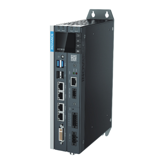
AC800 Series Intelligent Machine Controller Hardware User Guide 2 Product Information 2 Product Information The booksize all-metal AC800 controller delivers a variety of network interfaces and powerful motion control performance. The controller supports multiple interfaces, including up to 2 Gigabit Ethernet ports, 2 EtherCAT interfaces, 2 USB2.0 interfaces, 2 USB3.0 interfaces, 1 RS485 interface, 1 RS232 interface, and... -
Page 11: Components And Functions
AC800 Series Intelligent Machine Controller Hardware User Guide 2 Product Information 2.2 Components and Functions The AC800 series includes the following controllers and accessories: Product Type Description Model Serial No. Intel Core i7 U; 4 G memory; 128 G hard drive; 2 Booksize USB2.0 interfaces;... -
Page 12: Led State Indicators
AC800 Series Intelligent Machine Controller Hardware User Guide 2 Product Information Interface Name Description Rear earhook Standard component State indicator For the specific definition of the indicators, see section 2.2.2 Display and buttons For specific functions and operations, see section 6... -
Page 13: External Expansion Card Slot
2.2.4 External Expansion Card Slot AC800 series controller supports a multi-function expansion card, which can be used as an interface for CAN communication, optical fiber, COM, Ethernet port, and high-speed I/O. Figure 2-2 Expansion card slot 2.2.3 Display and Buttons... -
Page 14: Interfaces
AC800 Series Intelligent Machine Controller Hardware User Guide 2 Product Information (1) system operation (2) controller status (3) fault and commissioning (4) basic controller information: basic hardware information, software version, and IP address (5) upgrade and download progress 2.2.5 Interfaces... - Page 15 AC800 Series Intelligent Machine Controller Hardware User Guide 2 Product Information Name Function Description Type Standard DVI-D DVI socket Standard DVI-I socket, white plastic, with shielded housing communication The controller provides 4 USB interfaces, all of which support plug-and-play and hot plugging, and can connect up to 127 external devices. Two USB 2.0 and two USB 3.0.
-
Page 16: Spare Parts And Options
AC800 Series Intelligent Machine Controller Hardware User Guide 2 Product Information 2.2.6 Spare Parts and Options Ordering Name Illustration Description code RTC button battery 3 V, 230 mAh 09050002 ∅16.9 CR2032 ∅20.0± 0.15 70,000 Hours at 40 ℃ , 65% humidity,... -
Page 17: Product Specifications
AC800 Series Intelligent Machine Controller Hardware User Guide 3 Product Specifications 3 Product Specifications 3.1 Basic Specifications The AC800 series includes two controllers, AC802 and AC810, whose basic specifications are shown in the following table: Item AC801-0221-U0R0 AC802-0222-U0R0 AC810-0122-U0R0 AC812-0322-U0R0 Power supply 24 VDC (–20% to 20%) -
Page 18: Environmental Specifications
AC800 Series Intelligent Machine Controller Hardware User Guide 3 Product Specifications 3.2 Environmental Specifications The environmental specifications of the controller are shown in the following table: Item Parameter Type Operation Transport Storage Class IE33 IE22 IE12 Temperature -5–55℃ -40–70℃ -25–70℃... -
Page 19: Installation And Fixing
AC800 Series Intelligent Machine Controller Hardware User Guide 4 Installation and Fixing 4 Installation and Fixing 4.1 Installation Requirements 4.1.1 Installation Environment When installing the controller on the guide rail, take the operability, maintainability, and robustness into account. Do not install the module in a location which is subject to ■... -
Page 20: Safety Precautions
AC800 Series Intelligent Machine Controller Hardware User Guide 4 Installation and Fixing 4.1.3 Safety Precautions Precautions when installing the controller: ■ Before installation, ensure that the controller is powered off; ■ To avoid damage to the controller, do not drop or impact the controller's housing, terminal block,and connector;... -
Page 21: Installation Methods
AC800 Series Intelligent Machine Controller Hardware User Guide 4 Installation and Fixing 4.2.2 Installation Methods The booksize controller can be installed through a rear earhook (booksize) or a side earhook (wall- mounted) to be adapted to cabinets of different sizes. The controller must be tightened with four screws to a tightening torque of 1.2 N.m. -
Page 22: Installing And Removing The Battery
AC800 Series Intelligent Machine Controller Hardware User Guide 4 Installation and Fixing 2 Installation Install the fall in revere order. 4.4 Installing and Removing the Battery The battery can only be removed and installed after the fan is removed. Remove the fan as instructed in section 4.3 first. - Page 23 AC800 Series Intelligent Machine Controller Hardware User Guide 4 Installation and Fixing Installation 1) As shown in the figure below, insert the new expansion card ① into the card slot ② . Avoid hitting and scratching and ensure the direction is correct.
-
Page 24: Wiring
AC800 Series Intelligent Machine Controller Hardware User Guide 5 Wiring 5 Wiring 5.1 Wiring Instructions This section describes the precautions for wiring the controller. 5.1.1 Grounding A ground point is set on the power terminal of the controller and the rear earhook ( ). -
Page 25: Installation Of The Filter
AC800 Series Intelligent Machine Controller Hardware User Guide 5 Wiring Category Description Category I Ethernet and EtherCAT interfaces Category II Low-speed digital communication signals (RS232 and RS485) and DI/DO signals Category III Low-voltage AC power distribution cable or DC power cable (such as DC 24 V power... -
Page 26: Wiring Of Power Input Terminal
AC800 Series Intelligent Machine Controller Hardware User Guide 5 Wiring 5.2 Wiring of Power Input Terminal The power input terminal is a 3-pin screw-fixed pluggable terminal with a pitch of 5.08 mm. To facilitate wiring, replacement and maintenance, use a spring clamp crimping terminal. The following illustration... -
Page 27: Wring Of I/O Communication Interface
AC800 Series Intelligent Machine Controller Hardware User Guide 5 Wiring Figure 5-6 Wiring of User terminal 5.3.1 Wring of I/O Communication Interface 1 Definition of I/O communication interface Signal I/O communication Signal Description Function Function Description Name interface Name Starts the PLC... -
Page 28: Wiring Of Ups And Status I/Os
AC800 Series Intelligent Machine Controller Hardware User Guide 5 Wiring Item Input Signal (pins 1/3/5) Output Signal (pins 2/4) Isolation mode Optocoupler isolation Optocoupler isolation Short circuit-proof output 3 RS-485 specifications: RS485 communication supports the Modbus RTU protocol and free protocol. -
Page 29: Rs485 Bus Wiring Instructions
AC800 Series Intelligent Machine Controller Hardware User Guide 5 Wiring Wiring of P_OK power failure detection signal: See the above figure. When a power failure occurs, the signal turns from ON to OFF, and the PLC saves data and shuts down. -
Page 30: Rs232 Bus Wiring Instructions
AC800 Series Intelligent Machine Controller Hardware User Guide 5 Wiring Figure 5-11 Star Terminal wiring The controller provides three terminals (485+, 485- and GND) for RS485 communication. Ensure that the RS485 bus contains three cables, and the terminals are connected correctly. If you are using shielded cables, the shielding layer must be connected to the GND terminal, rather than any other location (including housings and equipment ground terminals). -
Page 31: Communication Specifications
AC800 Series Intelligent Machine Controller Hardware User Guide 5 Wiring Port Function LAN B Modbus/TCP communication port LAN C EtherCAT master port LAN D 5.5.1 Communication Specifications 1. Gigabit Ethernet specifications Number of ports and hardware characteristics 2 standard Ethernet interfaces: LAN A which supports standard MODBUS/TCP protocol, and LAN B which supports program download and monitoring. -
Page 32: Ethernet Cabling
AC800 Series Intelligent Machine Controller Hardware User Guide 5 Wiring 5.5.2 Ethernet Cabling Networking diagram With the Ethernet port, the controller can be connected point-to-point with devices such as a computer and HMI through an Ethernet cable. Figure 5-13 Connection between controller and PC The controller can also be connected to a hub or switch, which is further connected with other network devices, through an Ethernet cable to achieve multi-point connection. -
Page 33: Ethercat Cabling
AC800 Series Intelligent Machine Controller Hardware User Guide 5 Wiring 5.5.3 EtherCAT Cabling Networking diagram With the EtherCAT port, the controller can be connected to various servo drives, slave modules or expansion modules that support EtherCAT communication. Figure 5 -15 Connection between CPU module and other devices through EtherCAT port 5.5.4 Requirements on Communication Cable... -
Page 34: Display Interface
AC800 Series Intelligent Machine Controller Hardware User Guide 5 Wiring Cable Preparation Figure 5 -18 EtherCAT cable preparation Signal pins Signal (Ethernet 1000 Mbps) Signal Direction Signal Description Output Data transmission+ Output Data transmission- Input Data reception+ --(DC+*) --(bidirectional) Not used (data C+) -
Page 35: Usb Port
AC800 Series Intelligent Machine Controller Hardware User Guide 5 Wiring Illustration Signal Signal TMDS data 2- TMDS data 3+ TMDS data 2+ +5 V power supply TMDS data 2/4 mask GND (+5 V circuit) TMDS data 4- Hot plug detection... -
Page 36: Cable Selection And Preparation
AC800 Series Intelligent Machine Controller Hardware User Guide 5 Wiring 5.8 Cable Selection and Preparation 5.8.1 Cable Selection Applicable Cable Diameter Signal Material Name Chinese standard/ Power signal cable Pin terminal 0.8-2.5 18-12 User signal cable Pin terminal 0.2-1.5 24-16... - Page 37 AC800 Series Intelligent Machine Controller Hardware User Guide 5 Wiring ∅D2 ∅D1 Category Terminal Size Length of Metal Stripping Length Part L2 1.00mm² [H1.0/18D] 12 mm 15 mm 0.75mm² [H0.75/18D] 12 mm 14 mm Tubular end with sheath 0.50mm² [H0.5/16D]...
-
Page 38: Operating Instructions
AC800 Series Intelligent Machine Controller Hardware User Guide 6 Operating Instructions 6 Operating Instructions 6.1 Power-on safety precautions WARNING ◆ Do not touch the terminal when the power is on. Failure to comply may result in electric shock. ◆ Do not disassemble this product. Especially when the power is on or shortly after the power is turned off. Because high voltage can be generated by the voltage boost inside the power supply, which may cause electric shock. -
Page 39: Power-Off
6.2 Power-off safety precautions WARNING ◆ The AC800 series controller will continue to operate normally for a certain period of time when an instantaneous power failure occurs, so it may receive error signals from external devices affected by the instantaneous power failure. -
Page 40: Operations At Instantaneous Power-Off
AC800 Series Intelligent Machine Controller Hardware User Guide 6 Operating Instructions DC: below 22.5V DC:15ms 100-200ms After the power-off evaluation time, even if the voltage is reset, the PLC still stops running, as shown in the following figure: DC: below 22.5V... -
Page 41: Operations After Power-Off Estimation
The execution is terminated and the data is saved in the hard drive. 6.3 Display 6.3.1 Menus After the PLC is turned on, the BIOS starts and the main page, which includes the Inovance logo and self- test codes, displays. ■ If no error occurs, you will see the programming interface page;... -
Page 42: Main Page
AC800 Series Intelligent Machine Controller Hardware User Guide 6 Operating Instructions To prevent endless loop caused by improper programming, you can force the application program not to run at next PLC startup by pressing the combination key "Back" + "Enter", +, in the programming interface page. (see section 6.3.3.2 (4) for NOTE details). - Page 43 AC800 Series Intelligent Machine Controller Hardware User Guide 6 Operating Instructions (2) Network port information Network port Function Network port information Physical address [Note] Remarks screenprint Support factory LAN A recovery, see section 6.3.3.2 (5) EtherNET for details LAN B 1.
- Page 44 AC800 Series Intelligent Machine Controller Hardware User Guide 6 Operating Instructions will be ciphered. ■ After you input the last digit and press Enter, if the password is wrong, all digits will be cleared you have to re-enter the password.
- Page 45 AC800 Series Intelligent Machine Controller Hardware User Guide 6 Operating Instructions Requirements for download a. The USB drive contains the application package named Application.userprg, which is packaged and generated by InoProShop. b. The package is in the root directory of the USB drive (if there are multiple packages, only the package in the root directory is valid).
- Page 46 AC800 Series Intelligent Machine Controller Hardware User Guide 6 Operating Instructions 2.USB download A&B The network port information is shown in following table: Network port LAN A LAN B screenprint B info A info 192.168.2.88 192.168.1.88 Factory default 255.255.255.0 255.255.255.0 192.168.1 .1...
- Page 47 Startup error After the PLC starts, it performs the BIOS self-test and displays the Inovance logo and self-test codes. If an error is detected during the self-test, you will be led to the error page, which shows the error code and detailed information (for details, see Appendix I).
- Page 48 AC800 Series Intelligent Machine Controller Hardware User Guide 6 Operating Instructions displays to warn the user that the BIOS self-test codes have not been sent. You can return to the startup interface by pressing the Back key. Program and system error ■...
-
Page 49: Page Switchover
AC800 Series Intelligent Machine Controller Hardware User Guide 6 Operating Instructions 6.3.4 Page Switchover When you switch pages on the display panel: The screen will automatically turn off if there is no key operation for 15 minutes (the screen will not turn off when there is an error window). -
Page 50: Programming Tool
AC800 Series Intelligent Machine Controller Hardware User Guide 7 Programming Tool 7 Programming Tool 7.1 Obtaining the Programming Tool You can obtain the user programming software InoProShop and all kinds of documents of the controller by the following ways: ■... - Page 51 AC800 Series Intelligent Machine Controller Hardware User Guide 7 Programming Tool Steps Description Interface The installation wizard appears and prepares for the installation Click Next to start the installation Select the installation path and click Next -51-...
- Page 52 AC800 Series Intelligent Machine Controller Hardware User Guide 7 Programming Tool Steps Description Interface Select components that you want to install and click Next Click Next Click Next -52-...
- Page 53 AC800 Series Intelligent Machine Controller Hardware User Guide 7 Programming Tool Steps Description Interface Wait until the Installation Wizard Complete window appears, and click "Finish" to complete the installation. Language setting The default interface language of InoProShop is Simplified Chinese. If you need to switch to another language, click Tool - Options - International Settings on the main page of the software to select the language.
-
Page 54: Uninstalling Inoproshop
AC800 Series Intelligent Machine Controller Hardware User Guide 7 Programming Tool 7.2.3 Uninstalling InoProShop You can uninstall InoProShop directly from the Control Panel as follows: Quit InoProShop and ensure that Gateway is closed. If there is a CoDeSys icon in the task bar, right click the icon and select Exit to close Gateway. -
Page 55: Maintenance
AC800 Series Intelligent Machine Controller Hardware User Guide 8 Maintenance 8 Maintenance When using the controller and its accessories, users need to carry out daily or periodical inspections to ensure that the controller are always in the best condition. 8.1 Periodical Maintenance and Inspection The parts of the controller may deteriorate due to environmental conditions, therefore, periodical inspection is required. -
Page 56: Maintenance Of The Battery
AC800 Series Intelligent Machine Controller Hardware User Guide 8 Maintenance Item Description Standard Measure The design life of the battery at 25 ℃ is 5 years, and its service life is 0.75 to 5 Real-time years, which varies with the model and clock battery No "battery voltage low"... -
Page 57: Maintenance Of The Fan
AC800 Series Intelligent Machine Controller Hardware User Guide 8 Maintenance 8.3 Maintenance of the Fan Purpose of the fan If the temperature in the controller reaches or exceeds the predefined temperature, the fan will automatically start to cool down the controller. When the temperature of the controller drops below the fan stop temperature, the fan will stop. -
Page 58: Appendix
AC800 Series Intelligent Machine Controller Hardware User Guide Appendix Appendix Appendix 1 Process Codes and Error Codes during BIOS Startup Note: BIOS process coding and fault coding are independent of other fault codings of the controller. 1 The BIOS process code display is shown in the following figure:... - Page 59 AC800 Series Intelligent Machine Controller Hardware User Guide Appendix BIOS Code Description Process Code 0x98 Console input devices connect 0x99 Super IO Initialization 0x9A USB initialization is started 0x9C USB Detect 0x9D USB Enable 0xA0 IDE initialization is started 0xA2...
-
Page 60: Appendix 2 Controller Related Error Codes
AC800 Series Intelligent Machine Controller Hardware User Guide Appendix BIOS Code Description Process Code 0xE8 S3 Resume Failed 0xE9 S3 Resume PPI not Found 0xEA S3 Resume Boot Script Error 0xEB S3 OS Wake Error 0xF8 Recovery PPI is not available... - Page 61 AC800 Series Intelligent Machine Controller Hardware User Guide Appendix Error Code Description Remedy 1. Check that the termination resistor is set correctly 0x83 Modbus RTU1:CRC check failed 2. Improve the wiring, for example, by removing any possible source of interference...
-
Page 62: Appendix 3 Ethercat Related Fault Codes
AC800 Series Intelligent Machine Controller Hardware User Guide Appendix Appendix 3 EtherCAT Related Fault Codes Note: EtherCAT fault coding is independent of other fault codings of the controller The EtherCAT fault display is shown in the following figure: Error Code... - Page 63 AC800 Series Intelligent Machine Controller Hardware User Guide Appendix Error Code Description Remedy Read of product or vendor ID not 0x0A Restart the EtherCAT master successfull, more slaves in config as real? 1. Check that the device allows write access to this object...
- Page 64 AC800 Series Intelligent Machine Controller Hardware User Guide Appendix Error Code Description Remedy 0x84 Slave needs cold start 0x85 Slave needs INIT 0x86 Slave needs PREOP 0x87 Slave needs SAFEOP 0x88 Invalid input mapping 0x89 Invalid output mapping 0x8A Inconsistent settings...
- Page 65 Tel: +86-755-2979 9595 Fax: +86-755-2961 9897 http://www.inovance.com Suzhou Inovance Technology Co., Ltd. Add.: No. 16 Youxiang Road, Yuexi Town, Wuzhong District, Suzhou 215104, P.R. China *19011381A00* Tel: +86-512-6637 6666 Fax: +86-512-6285 6720 19011381A00 http://www.inovance.com Copyright Shenzhen Inovance Technology Co., Ltd.
Need help?
Do you have a question about the AC800 Series and is the answer not in the manual?
Questions and answers