
Related Manuals for heat-timer LR-II


Summary of Contents for heat-timer LR-II
- Page 1 INSTALLATION AND OPERATION MANUAL LONG RANGE (LR-II) WIRELESS TEMPERATURE MODULE FOR CONTROLS WITH RINET (INTERNET) COMMUNICATION HEAT-TIMER CORP. 059098–00 REV. C...
- Page 2 (4)Consulting an experienced radio/TV technician for assistance. The antenna supplied by Heat-Timer Corporation must be used (gain <= 6dB). It is recommended not to operate the device (transceiver) with persons closer than 20cm to the antenna.
-
Page 3: Table Of Contents
INITIAL LR-II WIRELESS TEMPERATURE MODULE CONFIGURATION PROGRAMMING THE SYSTEM ID LOCATING THE LR-II WIRELESS TEMPERATURE MODULE GENERAL GUIDELINES IN LOCATING THE LR-II WIRELESS TEMPERATURE MODULE IN A BUILDING MOUNTING THE LR-II WIRELESS TEMPERATURE MODULE POWERING THE LR-II WIRELESS TEMPERATURE MODULE... -
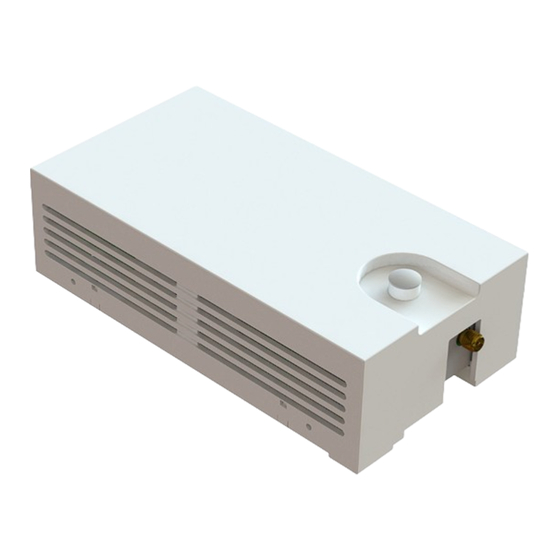
Page 4: Indicators And Connections
INDICATORS AND CONNECTIONS FIGURE 1 LR-II WTM, INDICATORS, AND CONNECTIONS ITEM DESCRIPTION ITEM DESCRIPTION 8 VAC Dedicated Transformer Input Status Indicators • Red LED blinks when transmitting data Temperature Sensor or Dry-Contact Switch Input • Green LED blinks when receiving data If both LEDs are blinking, no System ID has C Size Alkaline Batteries—Not Used... -
Page 5: Specifications
1 wake up button 3 LED for status display Dimensions 6" x 3– " x 1–¾" Mounting Wall or ceiling mount Temperature Sensors Heat-Timer Universal Temperature Sensor (HT # 90422–00) Switch Sensors Dry-Contact Only (No Voltage) HEAT-TIMER CORP. 059098–0 REV. C... -
Page 6: Installation Instructions
The LR-II Wireless Temperature Module (WTM) is designed to be utilized in a variety of large buildings, garden apartments, and in retrofit applications, giving both the accuracy and flexibility required to monitor those buildings' temperature and switches. -
Page 7: Required Materials (Not Supplied)
In these applications there may be a mixed of existing LR Wireless Temperature Modules, LR space sensor(s) and/or LR Repeaters along with LR-II Wireless Temperature Module, LR-II space sensor(s) and LR-II Repeaters. For existing Long Range Wireless networks, there may be a need to program the System ID into the new LR-II Wireless Temperature Module(s). -
Page 8: Initial Lr-Ii Wireless Temperature Module Configuration
LR-II WTM. NOTE If the MSI Installation Battery Pack is not available, then the LR-II WTM can be powered using (2) C size alkaline batteries. Make sure to observe the Positive (+) and Negative (–) terminals for each battery. - Page 9 INSTALLATION INSTRUCTIONS Observe the RED and GREEN status LEDs (3). When the LEDs stop blinking, the LR-II WTM has communicated to the MSI Hub and is ready to install. NOTE When properly communicating with the MSI Hub, the RED LED should blink when transmitting data and the GREEN LED should blink when receiving data.
-
Page 10: Programming The System Id
LR-II WTM, ensure the Battery Pack is not connected to the LR-II WTM. If the LR-II WTM is not installed and (2) C size Alkaline batteries are being used to supply power to the LR-II WTM, ensure the batteries are removed from the LR-II WTM. - Page 11 Hold the LR-II WTM close to the MSI Hub, then connect the MSI Installation Battery Pack (Heat-Timer P/N 904292–00) to the RS485 connector on the LR-II WTM or insert the two C size batteries. Ensure to observe the Positive (+) and Negative (–) terminals for each battery. If the LR-II WTM was installed with a 8V transformer, reconnect the transformer wires to the Input terminals on the LR-II WTM.
- Page 12 WTM was not properly clear of the previous System ID and did not communicate with the MSI Hub. Ensure the System ID was properly cleared from the LR-II WTM as outlined in the above Steps 2 through 7. If the problem persist, contact Heat Timer tech support for assistance.
-
Page 13: Locating The Lr-Ii Wireless Temperature Module
The mounting surface can be any wall or ceiling, and should be flat and strong enough to hold the weight of the LR-II WTM. DO NOT mount the LR-II WTM in a location where it will be exposed to heating, cooling, or humidity sources (such as near radiators, heating/cooling vents, windows, doors, or in a kitchen or bathroom. -
Page 14: Mounting The Lr-Ii Wireless Temperature Module
PROGRAMMING THE SYSTEM ID on page 10 have been completed before continuing. The LR-II WTM cover should already have been removed. Once an appropriate location to mount the LR-II WTM has been determine, the LR-II WTM base is ready to be mounted. -
Page 15: Powering The Lr-Ii Wireless Temperature Module
It is recommended the LR-II Wireless Temperature Module be provided with a power supply input from a 8 VAC (transformer is supplied P/N 210024–00). Only use the 8 VAC as a power source to avoid damage to the LR-II WTM. -
Page 16: Connecting The Wiring
DO NOT re-connect electrical power until ALL wiring to the LR-II WTM is completed. Failure to do so may result in severe personal injury or death. DO NOT share the LR-II WTM AC power transformer with other devices. This may cause problems with the wireless operation or permanent damage to the equipment. -
Page 17: Wiring The Sensor/Dry-Contact Switch
Do not run sensor wires in conduit with line voltage wiring. • If wiring a switch to the LR-II WTM in lieu of a temperature sensor, ensure the switch is a dry contact and that no voltage is applied to the switch. -
Page 18: Attaching Lr-Ii Wtm Indoor Antenna
ATTACHING LR-II WTM INDOOR ANTENNA The LR-II WTM is supplied with a rubberized external antenna that is intended only for indoor use. The antenna can be rotated around a swivel-point to change its direction in order to achieve the best possible signal strength. -
Page 19: Performing The Icms Configuration
Select SETUP SENSORS/ALARMS from the drop down menu on the left side of the screen. Select the Building/Control name from the drop down menu under CHOOSE BUILDING/CONTROL. Then select CONTINUE in the lower right corner of the screen. HEAT-TIMER CORP. 059098–0 REV. C... - Page 20 NOTE Each LR-II WTM is provide with a Sensor ID card and is labeled with the Sensor ID on the base of the LR-II WTM. Complete the Sensor Name that will allow easy identification in the location of the LR Repeater and select which floor the LR repeater is located.
-
Page 21: Testing And Operating The Lr-Ii Wtm
Send its value, transmission and reception power, and address; at predetermined intervals. POWER INPUT WIRING • In the Normal Mode, the LR-II WTM will transmit data to the LR Repeater or MSI Hub that can hear it. During that process no LED lights will blink. •... -
Page 22: Send One Packet Mode
INSTALLATION INSTRUCTIONS SEND ONE PACKET MODE • The LR-II WTM can be set to send a single data packet by clicking the SEND button once. Once press, the LR-II WTM RF Module LED will blink Red to indicate data transmission. This is useful when testing LR-II WTM transmission operation or after configuring the LR-II WTM on ICMS page. -
Page 23: Warranty
WARRANTIES AND LIMITATIONS OF LIABILITY AND DAMAGE: Heat-Timer Corporation warrants that it will replace, or at its option, repair any Heat-Timer Corporation manufactured product or part thereof which is found to be defective in material workmanship within one year from the date of installation only if the warranty registration has been properly filled out and returned within 30 days of the date of installation. - Page 24 20 NEW DUTCH LANE, FAIRFIELD, NJ 07004 PHONE: 973-575-4004 FAX: 973-575-4052 HEAT-TIMER.COM HEAT-TIMER CORP. 059098–00 REV. C...
Need help?
Do you have a question about the LR-II and is the answer not in the manual?
Questions and answers