
Related Manuals for heat-timer ETS-LT


Summary of Contents for heat-timer ETS-LT
- Page 1 INSTALLATION AND OPERATION MANUAL ETS-LT E L E C T R O N I C T E M P E R I N G S TAT I O N 059327–00 REV. C...
- Page 2 WARNING This Heat-Timer control is strictly an operating control; it should never be used as a primary limit or safety control. All equipment must have its own certified limit and safety controls required by local codes. The installer must verify proper operation and correct any safety problems prior to the installation of any Heat-Timer control.
-
Page 3: Table Of Contents
DAYLIGHT SAVING SUPPLIED MATERIALS MAIN MENU REQUIRED MATERIALS (NOT SUPPLIED) SETPOINT DESIGN CONSIDERATIONS HTLV SETPOINT SELECTING A LOCATION FOR THE ETS-LT ASSEMBLY HTLV TRIGGER DELAY RECOMMENDED CLEARANCE MODULATING GAIN GENERAL ELECTRICAL GUIDELINES SYSTEM STARTUP MENU MOUNTING THE ETS-LT ASSEMBLY SELECT DAYS... -
Page 4: Overview
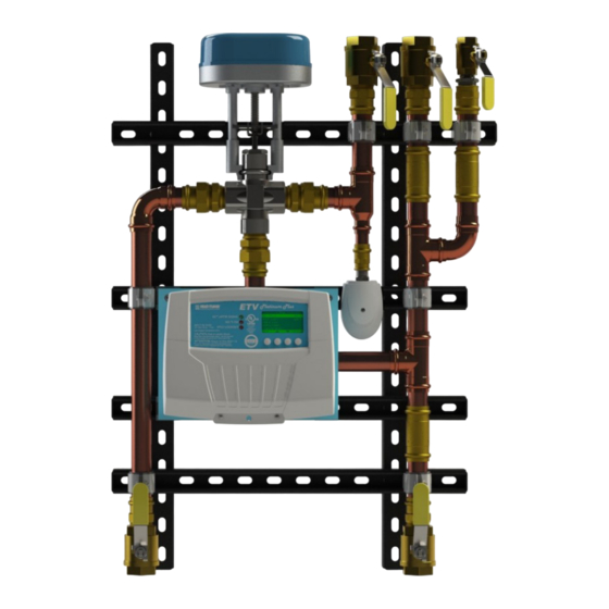
The ETS-LT assembly consists of the ETV valve with actuator, ETV Platinum Plus control module and a probe (direct immersion) sensor on the Mixed Outlet, piping from the valve. The ETV valve, control module and piping assembly components are mounted on a Unistrut frame that allows mounting on a wall. -
Page 5: Controls, Indicators, And Connections
CONTROLS, INDICATORS, AND CONNECTIONS FIGURE 1 ETS-LT CONTROLS, INDICATORS, AND CONNECTIONS ITEM DESCRIPTION ITEM DESCRIPTION Electronic Temperature Controller Boiler Feed Line (ETV Platinum Plus) Cold Water Line ETV Valve Body with Actuator Tempered Water Line Temperature Sensor Hot Water Line Recirculation Water Line 059327–00 REV. - Page 6 ETS-LT MODULE CONTROLS, INDICATORS, AND CONNECTIONS ITEM DESCRIPTION Output Status LEDs See “ETS-LT Control Module Output Status LEDs” on page 21. Digital Display See “Display and Variable-Function Buttons” on page 21. Variable-Function Buttons See “Display and Variable-Function Buttons” on page 21.
-
Page 7: Specifications
SPECIFICATIONS FIGURE 3 ETS-LT DIMENSIONS 059327–00 REV. C HEAT-TIMER CORP. -
Page 8: Ets-Lt Sizing
SPECIFICATIONS ETS-LT SIZING ETS MODELS PRESSURE DROP PSI ETS–75 ETS–100 ETS–125 5 GPM 5 GPM 10 GPM BUILDING RECIRC GALLONS PER MINUTE PIPE SIZE PART VALVE WEIGHT MODEL NUMBER HEAT SOURCE SIZE MIXED COLD RECIRC COLD SUPPLY ” ” ”... -
Page 9: Etv Platinum Plus Control Module
Voltage Input 24Vac 60Hz Power Consumption 18VA max Input Signal 0–10V Weight 2.6 lbs (1.2 kg) ETS-LT VALVE BODY Body and Trim 304 Stainless Steel Maximum Operating Temperature 300°F (149°C) Maximum Working Pressure 225 psi Stem Material 640 Stainless Steel 059327–00 REV. -
Page 10: Installation Instructions
INSTALLATION INSTRUCTIONS The installation process for ETS-LT consists of the following basic steps: Initial installation (see “Design Considerations” on page 10). Mounting the ETS-LT assembly (see page 11). Connecting the ETS-LT assembly power wiring (page 15). Upgrade/optional wiring the ETS-LT (see page 40). -
Page 11: Selecting A Location For The Ets-Lt Assembly
• The ETS-LT is too heavy and bulky for a single individual to lift and attempt to mount. It is recommended that a minimum of 3 people are needed. The ETS-LT assembly should be support by 2 individuals while the 3rd individual does the mounting. -
Page 12: Applications Using Wood Studs
Set the ETS-LT assembly down on the floor. Drill a 1/4” diameter by 2” deep hole in the center of each mark. Reposition the ETS-LT assembly on the wall and align with the newly drilled holes. Insert the lag screws and washers through the unistrut frame into the holes and loosely tighten. -
Page 13: General Piping Guidelines
Use unions (provided) to allow for servicing and, if required, removal of the valve and other components. • Include drain valves (provided) to assist in servicing of the ETS-LT assembly. • Use a generous amount of pipe thread sealant. DO NOT use pipe thread tape. When using the valve in a domestic water application, ensure the thread sealant is compliant with domestic water application and meets NSF 61 requirements. -
Page 14: Recirculation Pump Sizing
Stagnant water provides ideal conditions for the growth of bacteria, such as Legionella. The flow switch should be located on the MIXED outlet field piping above the ETS-LT assembly. Activation of the flow switch should be at the lowest potential draw of the system. -
Page 15: Connecting The Ets-Lt Assembly Power Wiring
WARNING ELECTRICAL SHOCK HAZARD! To avoid the risk of electric shock, DO NOT re-connect electrical power until ALL wiring to the ETS-LT is completed. Failure to do so may result in severe personal injury or death. 059327–00 REV. C HEAT-TIMER CORP. -
Page 16: Ets-Lt Optional Field Wiring
Connect one of the 24Vac transformer outputs to the actuator COMMON terminal on Terminal Block F of the Motorized Ball Valve. Connect the second 24Vac transformer output to the HTLV Common terminal (12) on the ETS-LT Control module. Connect the HTLV normally closed (NC) terminal (11) on the ETV module to the Motorized Ball Valve actuator CLOSE terminal on Terminal Block F. -
Page 17: Wiring The Htlv Lockout Alarm (Optional)
WIRING THE HTLV LOCKOUT ALARM (OPTIONAL) NOTE The ETS-LT Control Module does not source power to the HTLV Lockout terminals. An external power source is required and must be connected in series as shown in the diagram. Run the alarm wire and the external power source wire through knockouts located on the bottom of the ETS-LT Control Module enclosure. -
Page 18: Wiring The 4-20Ma Remote Setpoint
WIRING THE 4–20MA REMOTE SETPOINT NOTE The ETS-LT Control Module does not source power to the 4–20mA terminals. The EMS system must provide the excitation voltage. Run the 4–20mA Setpoint wires through a knockout located on the bottom of the ETS-LT Control Module enclosure. -
Page 19: Completing The Wiring
Do not re-install the Enclosure wire cover at this point as access to the PROGRAM/RUN switch is needed for programing of the ETS-LT module. With power supplied to the ETS-LT, the power loss capacitor of the valve actuator requires about 2 minutes to fully charge. -
Page 20: Factory Wiring
INSTALLATION INSTRUCTIONS FACTORY WIRING ETV PLATINUM PLUS CONTROL MODULE SYSTEM SENSOR HTC ACTUATOR (BLUE OVAL) WIRE TERMINALS FIGURE 6 ETS-LT FACTORY WIRING DIAGRAM HEAT-TIMER CORP. 059327–00 REV. C... -
Page 21: Startup
DESCRIPTION Actuator Signal Indicates the change in the mixing valve opening. Any time the ETS-LT Control Module changes the valve opening, the LED will turn on for approximately one second. If the LED remains lit, the control is sending the Actuator a “fully open” or “fully close”... -
Page 22: Default Display
The area above the variable function buttons that describe the button’s function may not be displayed due to inactivity. Pressing the far-right button in the default display will enter into the Menu screen. 2, 9 HEAT-TIMER CORP. 059327–00 REV. C... -
Page 23: Display Icons And Messages
This message will alternate with the date and time message. ALARM MESSAGES The ETS-LT logs all alarm messages, with the date and time of their occurrence (See “Alarm Log” on page 37). The following alarm messages may be displayed by the ETS-LT. -
Page 24: Setting The Display Contras
After resetting the control, the ETV Platinum Plus will go to the Startup menu (See “System Startup Menu” on page 25). --- SENSOR FAULT --- All Off All On ▲ ▼ BACK SAVE --- SENSOR FAULT --- All Off All On ▲ ▼ BACK SAVE HEAT-TIMER CORP. 059327–00 REV. C... -
Page 25: Ets-Lt Programming Menus
SYSTEM STARTUP MENU If the System Startup menu screens to not appear, the ETV Platinum Plus has When the ETS-LT Control Module is first powered-on already been configured. To check the and initialization is complete, the System Startup menu configuration or to make changes, select screens appear. -
Page 26: Control Mode
This option changes the sensors’ display and all temperature settings standard to Fahrenheit or Celsius. SETPOINT INPUT Selections: Local Input, Remote 4–20mA Default: Local Input If Remote 4-20mA is selected: Default: 60°F/16°C 4mA range: (40°F/4.5°C to 200°F/93°C) HEAT-TIMER CORP. 059327–00 REV. C... -
Page 27: Aux1/Aux2 Input
Menu Path: /System Startup > Display Unit > Setpoint Input Description: The ETS-LT Control Module can maintain a setpoint temperature either by selecting the temperature locally at the control or by receiving a remote setpoint temperature as a 4–20mA signal from EMS. -
Page 28: Hot Supply Comp
- EMS INPUT MODE - ------ SET POINT ---- Disable ▲ ▼ BACK SAVE With Enable Rese ▲ ▼ BACK SAVE 100° ▲ ▼ BACK SAVE ------ SET POINT ---- HEAT-TIMER CORP. 327–00 REV. C -EMS 4ma SETPOINT - With... -
Page 29: Modulation Type
With Rese ▲ ▼ BACK SAVE Rese ▲ ▼ 80° W BACK SAVE With Description: The ETS-LT Control Module is capable of operating a variety With a ▲ ▲ ▼ ▼ 80° W BACK SAVE BACK SAVE Rese With Reset of 3-way valve Actuators. -
Page 30: Daylight Saving
FOR ALL CIRCUITS Lag Delay 0min INPUT RATINGS: <More Settings> Point1 Min Target 115VAC 60Hz , 12VA MAX ▲ ▼ SELECT BACK HEAT-TIMER CORP. 059327–00 REV. C USE COPPER CONDUCTORS ONLY ----- SETTINGS 2 ---- Outdoor Temperature (in °F) Standby Time 10min... -
Page 31: Setpoint
0-10v 0-5v -- SYSTEM RUN-ON -- 0-5v 2-10v -- SYSTEM RUN-ON -- 2-10v 5 min 1-5v 5 min 1-5v ▲ ▼ BACK SAVE ▲ ▼ BACK SAVE ▲ ▼ BACK SAVE ▲ ▼ BACK SAVE 059327–00 REV. C HEAT-TIMER CORP. -
Page 32: Htlv Setpoint
------ SETBACK ------- ▲ ▼ --- LEAD STAGES --- BACK SAVE ▲ ▼ --- LEAD STAGES --- BACK SAVE Cond Lead HEAT-TIMER CORP. 059327–00 REV. C Cond Lead Non-Cond Lead Non-Cond Lead ▲ ▼ --- LEAD STAGES --- BACK SAVE ▲ ▼... -
Page 33: Modulating Gain
0min Soft-Off Delay 45sec ▲ ▼ BACK SAVE ------ GAIN ------ ▲ ▼ BACK SAVE ---- LAG DELAY ---- ---- LAG DELAY ---- 0 min 0 min ▲ ▼ BACK SAVE ▲ ▼ BACK SAVE 059327–00 REV. C HEAT-TIMER CORP. -
Page 34: System Startup Menu
BACK SAVE OUTDOOR SENSOR TRIM ▲ ▼ BACK SAVE -- SOFT-OFF DELAY -- 45 sec ▲ ▼ BACK SAVE -- STAGE A TRIM -- Output Trim +0.0 <Prev Stage> <Next Stage> ▲ ▼ SELECT BACK HEAT-TIMER CORP. 059327–00 REV. C... -
Page 35: Select Days
The new Schedule Setpoint temperature is displayed on the screen with an asterisk (for example, 130F*). All Temp. settings for each day of the week must be set to guarantee that the default setting is replaced 059327–00 REV. C HEAT-TIMER CORP. -
Page 36: Maintenance Menu
BACK SAVE 4-20ma 4-20ma Disabled Disabled 1-5v 1-5v 4-20ma 4-20ma Disabled Disabled 1-5v 1-5v 0-10v 0-10v BACK SAVE HEAT-TIMER CORP. BACK 059327–00 REV. C SAVE BACK SAVE BACK SAVE 0-10v 0-10v BACK SAVE BACK SAVE BACK SAVE 0-5v 0-5v BACK... -
Page 37: Alarm Log
45sec ▲ ▼ BACK SAVE -EMS 4ma SETPOINT - ▲ ▼ BACK SAVE -EMS 4ma SETPOINT - ▲ ▼ BACK SAVE ▲ ▼ BACK SAVE -EMS 20ma SETPOINT- -EMS 20ma SETPOINT- 059327–00 REV. C HEAT-TIMER CORP. ▲ ▼ BACK SAVE... -
Page 38: Lockout Menu
To reset the lockout, the conditions causing the lockout must be corrected first. Then, the lockout can be reset using the Reset Lockout menu. If the lockout was reset before the conditions are corrected, the lockout output will immediately be re-activated. HEAT-TIMER CORP. 059327–00 REV. C... -
Page 39: Calibrating The Actuator
The green and red LEDs start blinking, indicating calibration has started. The Actuator moves the valve stem up and down. Calibration is complete when the green LED is steady-on or blinking. Replace the Actuator cover. Open the valve feeding the tempering valve HOT port. 059327–00 REV. C HEAT-TIMER CORP. -
Page 40: Ets-Lt Control Module Wiring
The information in this section is intended only for field replacement of the ETV Platinum Plus module or for upgrading the ETS-LT assembly for communications options. Remove the Enclosure Wiring Cover (1) by removing the two lower screws (2) holding it to the base (3), and then remove the Display Module (4) by removing the two middle screws (5) holding it to the base. - Page 41 ETS-LT CONTROL MODULE WIRING Turn the ETS-LT Control Module display module (1) over to reveal the battery (2) circuit board. Remove the plastic tab to activate the battery. NOTE The battery is a coin lithium battery (CR2032—Heat Timer P/N 020002–00) that is used to maintain the control’s date and time during power outages.
-
Page 42: Ets-Lt Control Module Communications
ETS-LT CONTROL MODULE WIRING ETS-LT CONTROL MODULE COMMUNICATIONS WIRING (OPTIONAL) The ETS-LT Control Module can be connected to a network using either an internet (RINET), BACnet (IP or MSTP), or ModBUS connection. INTERNET (RINET) COMMUNICATIONS WIRING (OPTIONAL) To connect the ETS-LT Control Module to the internet: Run a CAT5 cable from the modem or router through a knockout located on the bottom of the ETS-LT Control Module enclosure. -
Page 43: Piping Diagrams
PIPING DIAGRAMS ETS-LT FIGURE 7 ETS SIMPLEX PIPING DIAGRAM HEAT-TIMER CORP. 059327–00 REV. C... -
Page 44: Troubleshooting
Turn power to the ETS-LT Control Module Control Module off then back on. Display shows sensor Sensor disconnected. Verify the sensor is properly connected to the ETS-LT “Open”. Control Module Control Module. Defective sensor, wires, Short the sensor input wires. The display should or ETS-LT Control Module read “Short”. - Page 45 13 and 15. If the Modulation Output % was at 40% (see “Default Display” on page 22), the signal should read 4Vdc. If it did not, the ETV control is damaged. Replace the ETS-LT Control Module. Actuator manual override Ensure the actuator is not in manual override.
-
Page 46: Notes
NOTES HEAT-TIMER CORP. 059327–00 REV. C... -
Page 47: Warranty
WARRANTIES AND LIMITATIONS OF LIABILITY AND DAMAGE: Heat-Timer Corporation warrants that it will replace, or at its option, repair any Heat-Timer Corporation manufactured product or part thereof which is found to be defective in material workmanship within one year from the date of installation only if the warranty registration has been completed online within 30 days of the date of installation. - Page 48 20 NEW DUTCH LANE, FAIRFIELD, NJ 07004 PHONE: 973-575-4004 FAX: 973-575-4052 HEAT-TIMER.COM...
Need help?
Do you have a question about the ETS-LT and is the answer not in the manual?
Questions and answers