Table of Contents
Advertisement
Quick Links
Advertisement
Table of Contents

Related Manuals for Air Lift LoadLIFTER 5000 57396


Summary of Contents for Air Lift LoadLIFTER 5000 57396
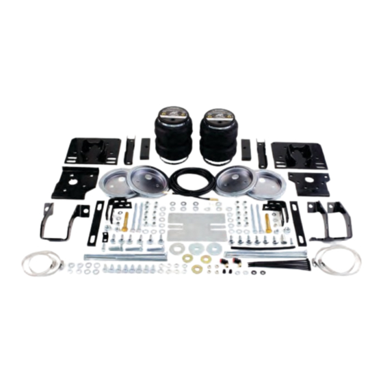
- Page 1 Kit 57396 Ford F-250/F-350/F-450 (Single and Dual Rear Wheel) 4-Wheel Drive INSTALLATION GUIDE For maximum effectiveness and safety, please read these instructions completely before proceeding with installation. Failure to read these instructions can result in an incorrect installation.
-
Page 3: Table Of Contents
TABLE OF CONTENTS Introduction ........2 Important Safety Notice . -
Page 4: Introduction
Air Lift Company reserves the right to make changes and improvements to its products and publications at any time. For the latest version of this manual, contact Air Lift Company at (800) 248-0892 or visit our website at www.airliftcompany.com. -
Page 5: Installation Diagrams
LoadLifter 5000 Installation Diagram - Driver Side O or N* fig. 1a NOTE: Lower Bracket sits on jounce bumper strike plate. See fig. 13a & 13b on page 12. * NOTE: If you have a fifth wheel hitch installed that has side plates along the frame, use the existing hardware removed. -
Page 6: Installation Diagram - Passenger Side
LoadLifter 5000 Installation Diagram - Passenger Side * NOTE: Use 3/4” flat washer (AA) if using 3/4” fifth wheel hitch hardware removed. R or AA* P or N** ** NOTE: If you have a fifth wheel hitch installed that has side plates along the frame, use the existing hardware removed. -
Page 7: Hardware And Tools Lists
5/16” Lock Washer ......2 21230 Valve Caps ..........2 21233 5/16” Hex Nut ........2 21234 Rubber Washer ........2 34924 Heat Shield Kit ........1 Missing or damaged parts? Call Air Lift customer STOP! service at (800) 248-0892 for a replacement part. MN-770... -
Page 8: Installing The Loadlifter 5000 System
LoadLifter 5000 Installing the LoadLifter 5000 System GETTING STARTED 1. Raise the vehicle and support the axle with jack stands, setting the jack stands as wide as possible on the axle. And/or support the vehicle in a way (safely) that will allow the axle to be dropped if using a hoist of some kind (fig. -
Page 9: Installing The Braces
LoadLifter 5000 INSTALLING THE BRACES NOTE Gas engine models have emission lines on the inside of the frame. If your model truck has emission lines running along the inside of the frame rail (fig. 4), it will be necessary to relocate those lines as follows: Carefully push the line holder out of the frame above the axle. -
Page 10: Passenger Side Brace Installation
LoadLifter 5000 2. If you have no fifth wheel hitch or if you have the standard equipment Reese fifth wheel hitch that was purchased on the truck from Ford, in the frame there is a slot that is forward of the M8 bolt just installed, insert the ½”-13 x 1.25” hex cap screw (O) and flat washer (W) through the brace and frame (from the inside out). -
Page 11: Bellows And Bracket Assembly
LoadLifter 5000 1. Set the right upper brace (B) into the passenger side frame rail (fig. 7). R or A A * P or N** * See footnote in fig. 1b ** See footnote in fig. 1b fig. 7 2. If you have no fifth wheel hitch or if you have the standard equipment Reese fifth wheel hitch that was purchased on the truck from Ford, insert the ½”-13 x 1.50”... - Page 12 LoadLifter 5000 3. Insert one long carriage bolt (EE) into the lower bracket (A) (fig. 8). NOTE The long carriage bolt will be behind the axle once the assembly is installed on the axle. Insert long carriage bolt (EE) in Passenger Side these square holes in the lower Use this hole...
-
Page 13: Attaching The Assembly To The Frame
LoadLifter 5000 8. Set the spacer (H) over both long carriage bolts (figs. 11 and 12). The hole in the flat spacer (H) is offset. Install the spacer so that the wide portion faces the NOTE outside of the vehicle (figs. 11 and 12). fig. - Page 14 LoadLifter 5000 NOTE: Passenger side shown Lower bracket Jounce bumper strike plate (located above axle) fig. 13a fig. 13b 3. Set the right (passenger side) assembly into position on the jounce bumper strike plate the same way the left side was positioned (fig. 1b and 7). 4.
-
Page 15: Attaching The Lower Bracket To The Axle
LoadLifter 5000 ATTACHING THE LOWER BRACKET TO THE AXLE 1. Insert a long 3/8” bolt (CC) and flat washer (V) through the top round hole of the four hole locating bracket (K). (fig. 15). NOTE Use the hole that is closest to the leaf spring. NOTE: Lower Bracket sits on jounce bumper strike plate. -
Page 16: Installing The Air Lines
LoadLifter 5000 INSTALLING THE AIR LINES 1. Choose a convenient location for mounting the inflation valves. Popular locations for the inflation valve are: a. The wheel well flanges b. The license plate recess in bumper c. Under the gas cap access door d. -
Page 17: Installing The Heat Shield
LoadLifter 5000 movement that might pull on the air line. Option 1 fig. 18 Option 2 7. Cut off the air line, leaving approximately 12” of extra air line. A clean square cut will ensure against leaks. Insert the air line into the air fitting. This is a push-to-connect fitting. -
Page 18: Checking For Leaks
DO NOT CUT OFF THE AIR LINE COMPLETELY AS THIS WILL USUALLY NICK THE CAUTION BARB AND RENDER THE FITTING USELESS. 3. If the preceding steps have not resolved the problem, call Air Lift customer service at (800) 248-0892. MN-770... -
Page 19: Before Operating
LoadLifter 5000 Before Operating INSTALLATION CHECKLIST (To be completed by installer) Clearance test — Inflate the air springs to 60 PSI and ensure there is at least ½” clearance around each bellow, away from anything that might rub against them. Be sure to check the tire, brake drum, frame, shock absorbers and brake cables. -
Page 20: Maintenance Guidelines
4. Look for a kink or fold in the air line. Reroute as needed. If the preceding steps do not solve the problem, it is possibly caused by a failed air spring — either a factory defect or an operating problem. Please call Air Lift at (800) 248-0892 for assistance. MN-770... -
Page 21: Frequently Asked Questions
No. Adding air springs will not change the weight ratings (GAWR, GCWR and/or GVWR) of a vehicle. Exceeding the GVWR is dangerous and voids the Air Lift warranty. Q. Is it necessary to keep air in the air springs at all times and how much pressure will they need? The minimum air pressure should be maintained at all times. -
Page 22: Guidelines For Adding Air
LoadLifter 5000 Guidelines for Adding Air 1. Start with the vehicle level or slightly above. 2. When in doubt, always add air. 3. For motorhomes, start with 50-100 PSI in the rear because it can be safely assumed that it is heavily loaded. 4. -
Page 23: Warranty And Returns Policy
Air Lift at (800) 248-0892 in the U.S. and Canada (elsewhere, (517) 322-2144) for a Returned Materials Authorization (RMA) number. Returns to Air Lift can be sent to: Air Lift Company • 2727 Snow Road • Lansing, MI • 48917. -
Page 24: Replacement Information
LoadLifter 5000 Replacement Information If you need replacement parts, contact the local dealer or call Air Lift customer service at (800) 248-0892. Most parts are immediately available and can be shipped the same day. Contact Air Lift Company customer service at (800) 248-0892, first if: •... - Page 28 Thank you for purchasing Air Lift products — the professional installer’s choice! Air Lift Company • 2727 Snow Road • Lansing, MI 48917 or PO Box 80167 • Lansing, MI 48908-0167 Toll Free (800) 248-0892 • Local (517) 322-2144 • Fax (517) 322-0240 • www.airliftcompany.com...
Need help?
Do you have a question about the LoadLIFTER 5000 57396 and is the answer not in the manual?
Questions and answers