Table of Contents
Advertisement
Advertisement
Table of Contents

Subscribe to Our Youtube Channel
Related Manuals for Air Lift 57365


Summary of Contents for Air Lift 57365
- Page 1 Guide S E R I E S Dodge/RAM 1500 Kits 57365 | 88365 | 89365 For maximum effectiveness and safety, please read these instructions completely before proceeding with installation. Failure to read these instructions can result in an incorrect installation.
- Page 2 IDENTIFYING THE DIFFERENCES BETWEEN KITS Should you need to contact Air Lift customer service, you will need to know which kit you are inquiring about: standard LoadLifter 5000, LoadLifter 5000 Ultimate or LoadLifter 5000 Ultimate Plus. The kits are easily identifiable by looking at the roll plates and air lines.
-
Page 3: Table Of Contents
TABLE OF CONTENTS Installation Diagram . . . . . . . . . . . . . . . . . . . . . . . . . . . . . . . . . . . 2 Hardware and Tools Lists . -
Page 4: Installation Diagram
DO NOT SCALE DRAWING TITLE THIS DRAWING IS THE PROPERTY OF THE AIR LIFT COMPANY AND IS NOT TO BE REPRODUCED, COPIED, LOANED, OR OTHERWISE DISPOSED OF, DIRECTLY, OR INDIRECTLY WITHOUT THE WRITTEN APPROVAL OF THE AIR LIFT COMPANY. THE ACCEPTANCE OF THIS DRAWING WILL BE CONSTRUED AS AN ACCEPTANCE OF THE FOREGOING CONDITIONS, AND AS AN ADMISSION OF THE EXCLUSIVE OWNERSHIP IN AND TO THE DRAWING OF THE AIR LIFT COMPANY, P.O. -
Page 5: Hardware And Tools Lists
21709 Fill valve with cap & nut .......... 2 21813 AN to PTC fitting ............ 2 20084 Air line assembly ............. 1 Missing or damaged parts? Call Air Lift customer Missing or damaged parts? Call Air Lift customer STOP! service at (800) 248-0892 for a replacement part. -
Page 6: Introduction
Air Lift Company reserves the right to make changes and improvements to its products and publications at any time. For the latest version of this manual, contact Air Lift Company at (800) 248-0892 or visit airliftcompany .com. -
Page 7: Installing The Loadlifter 5000 Series System
LoadLifter 5000 Series Installing the LoadLifter 5000 Series System GETTING STARTED In order to install the upper frame brackets (A), it will be necessary to remove the coil springs as follows: 1. Lift the vehicle up and support the frame with jack stands. Leave enough room to drop the axle down low enough to remove the coil springs (Fig. - Page 8 LoadLifter 5000 Series 5. Grind the welds off the jounce bumper cups that attach them to the jounce bumper frame bracket (Fig. 5). Remove and discard from both sides of the vehicle. fig. 5 6. Grind the remaining welds flush to the frame (Fig. 6). Spray the frame with paint or undercoating to cover the bare surface after grinding (Fig.
- Page 9 LoadLifter 5000 Series 8. Thread the nylon lock nut on the M8 bolt only enough to allow the bolt to slide freely in the slot. This will allow you to align the frame bracket correctly. 9. Set the frame bracket (with the socket head bolt in it), on the frame, with the flange pointing up.
- Page 10 LoadLifter 5000 Series 12. Center-punch the frame and drill a 1/4” hole (Fig. 13). Start a 5/16” self-tapping screw (K) into the hole, making sure it is straight, and tighten it enough to form the threads needed to set the screw (Fig. 13). Remove the screw once threads are formed.
-
Page 11: Assembling The Air Springs
LoadLifter 5000 Series 16. Once the frame brackets have been installed on both sides, the stock suspension can be put back together. 17. Set the coil springs back into position using the index marks from the previous step and raise the axle back up making sure the spring indexes into the top and bottom spring seats correctly. - Page 12 LoadLifter 5000 Series 4. Attach the upper air spring bracket using two 3/8” hex-head bolts (H), two lock washers (I) and two flat washers (J). Torque to no more than 20 lb.-ft. (27Nm) Repeat for the opposite side. Figure 18 shows both upper assemblies. fig.
-
Page 13: Installing The Assemblies
LoadLifter 5000 Series INSTALLING THE ASSEMBLIES 1. Index a 3/8” carriage bolt (L) into the opening on the front of the driver’s side assembly as shown (Fig. 21). fig. 21 2. Drop the axle again to gain clearance to put the two assemblies into position on the axle. - Page 14 LoadLifter 5000 Series 4. Insert another 3/8” carriage bolt (L) through the remaining hole in the front side of the bracket (Fig. 24). fig. 24 5. It will be necessary to use a socket with an extension to reach the inside threads on the carriage bolt previously set into position (Fig.
- Page 15 LoadLifter 5000 Series 7. Raise the axle back up while aligning the air spring mounting plate’s carriage bolts, with the frame mounting bracket holes. Cap all carriage bolts, once in position, with 3/8” serrated lock nuts (N) and torque all the installed nuts to 31 lb.-ft. (42Nm) (Fig.
-
Page 16: Installing The Air Lines
Air Line Setup Without Compressor System Vehicle body Flat Braided stainless steel LoadLifter 5000 Series air line to air spring or bumper Hex nuts Installing the Air Lines Schrader valve Air line hex nut Air lines are routed from the air springs to Schrader valves. LoadLifter 5000 Series air Star washer lines come in two styles: nylon and braided stainless steel. -
Page 17: Installing Braided Stainless Steel Air Lines
LoadLifter 5000 Series INSTALLING BRAIDED STAINLESS STEEL AIR LINES KEEP THE AIR LINE AWAY FROM THE FUEL LINE, BRAKE LINES AND ELECTRICAL CAUTION WIRES. 1. Use zip ties to secure Air Line Setup Without Compressor System the air line to fixed points Vehicle body Flat Braided stainless steel... -
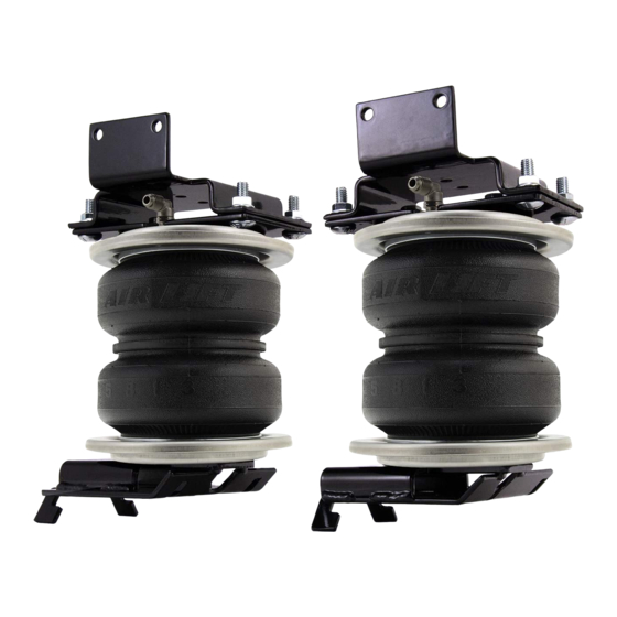
Page 18: Finished Installation Photos
LoadLifter 5000 Series Finished Installation Photos 1. Back view of left (driver’s) side assembly (Fig. 36). fig. 36 2. Back view of right (passenger’s) side assembly (Fig. 37). fig. 37 MN-1052... -
Page 19: Before Operating
DO NOT CUT OFF THE AIR LINE COMPLETELY AS THIS WILL USUALLY NICK THE CAUTION BARB AND RENDER THE FITTING USELESS. 3. If the preceding steps have not resolved the problem, call Air Lift customer service at (800) 248-0892. MN-1052... -
Page 20: Installation Checklist
Heat test — Be sure there is sufficient clearance from heat sources, at least 6” (152mm) for air springs and air lines. If a heat shield was included in the kit, install it. If there is no heat shield, but one is required, call Air Lift customer service at (800) 248-0892. -
Page 21: Product Use, Maintenance And Servicing
Operating the vehicle below the minimum air spring pressure will void the Air Lift warranty. 5. When increasing load, always adjust air pressure to maintain normal ride height. Increase or decrease pressure from the system as necessary to attain normal ride height for optimal ride and handling. -
Page 22: Tuning The Air Pressure
LoadLifter 5000 Series TUNING THE AIR PRESSURE Pressure determination comes down to three things — level vehicle, ride comfort and stability. 1 . Level vehicle If the vehicle’s headlights are shining into the trees or the vehicle is leaning to one side, then it is not level (Fig. -
Page 23: Troubleshooting Guide
Q . Will installing air springs increase the weight ratings of a vehicle? No. Adding air springs will not change the weight ratings (GAWR, GCWR and/ or GVWR) of a vehicle. Exceeding the GVWR is dangerous and voids the Air Lift warranty. - Page 24 LoadLifter 5000 Series Notes MN-1052...
- Page 25 LoadLifter 5000 Series Notes MN-1052...
- Page 26 LoadLifter 5000 Series Notes MN-1052...
-
Page 27: Limited Warranty And Return Policy
For additional warranty information contact Air Lift Company customer service. Replacement Part Information If replacement parts are needed, contact the local dealer or call Air Lift customer service at (800) 248-0892. Most parts are immediately available and can be shipped the same day. - Page 28 (517) 322-2144. For calls outside the U.S. or Canada, dial (517) 322-2144. Air Lift Company • 2727 Snow Road • Lansing, MI 48917 or P.O. Box 80167 • Lansing, MI 48908-0167 Printed in the USA JJC-1117...
Need help?
Do you have a question about the 57365 and is the answer not in the manual?
Questions and answers