Nibe F370 Installer Manual
Exhaust air heat pump
Hide thumbs
Also See for F370:
- Installer manual (88 pages) ,
- User manual (84 pages) ,
- Installation instructions manual (12 pages)
Table of Contents
Advertisement
Quick Links
Advertisement
Table of Contents

Related Manuals for Nibe F370


Summary of Contents for Nibe F370
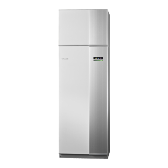
- Page 1 Installer manual Exhaust air heat pump NIBE F370 Stainless IHB EN 2340-1 M13247...
- Page 2 Quick guide Navigation Ok button (confirm/select) Back button (back/undo/exit) Control knob (move/increase/reduce) A detailed explanation of the button functions can be found on page 38. How to scroll through menus and make different settings is described on page 40. Set the indoor climate INDOOR CLIMATE HOT WATER HEAT PUMP...
-
Page 3: Table Of Contents
General ventilation connection Item register Ventilation flow Adjusting ventilation Contact information Dimensions and ventilation connections 5 Electrical connections General Connections Settings Optional connections Connecting accessories 6 Commissioning and adjusting Preparations Filling and venting Start-up and inspection NIBE F370 Table of Contents... -
Page 4: Important Information
NOTE mulate, and must be frost-proof. Work on refrigerant systems must F370 must be installed via an isolator be carried out by personnel who switch. The cable area has to be dimen- have knowledge and experience of sioned based on the fuse rating used. -
Page 5: Safety Precautions
The following checks must be carried out vice technician whether there is a possible for installations that use combustible refri- flammable atmosphere or not. Ensure that gerants. the refrigerant detector is suitable for NIBE F370 Chapter 1 | Important information... - Page 6 (the leak tra- When repairing sealed components, all cing equipment must be calibrated in an electrical supply must be disconnected area completely free from refrigerant). The from the equipment that is being repaired Chapter 1 | Important information NIBE F370...
- Page 7 Perform an additional leak test be- Compressed air and oxygen must not be fore leaving the installation. used. NIBE F370 Chapter 1 | Important information...
- Page 8 When the containers have been filled that it is working correctly and has been correctly and the process is complete, properly maintained. Associated electrical close all shut-off valves in the equip- components must be sealed, to prevent ig- Chapter 1 | Important information NIBE F370...
-
Page 9: Serial Number
Serial number The serial number can be found at the bottom right of the front cover, in the info menu (menu 3.1) and on the type plate (PZ1). NIBE F370 Chapter 1 | Important information... -
Page 10: Inspection Of The Installation
Pressure in the climate system Hot water (page 19) Mixing valve Safety valve Electricity (page 22) Connections Main voltage Phase voltage Fuses heat pump Fuses property Outside sensor Room sensor Current sensor Safety breaker Earth circuit-breaker Chapter 1 | Important information NIBE F370... -
Page 11: Delivery And Handling
10 mm is left to reduce the risk of noise and of any vibrations being propagated. Check that F370 has not been damaged during transport. However, the F370 can be carefully laid on its back when being moved into the building. The centre of gravity is in the top section. -
Page 12: Supplied Components
SIDE PANELS Remove the screws from the lower edge of the front Remove the screws from the upper and lower edges. panel. 3. Lift the panel out at the bottom edge and up. Chapter 2 | Delivery and handling NIBE F370... -
Page 13: Removing Parts Of The Insulation
3. Move the panel backwards and slightly to the side. 4. Assembly takes place in the reverse order. Removing parts of the insulation Parts of the insulation can be removed to facilitate the in- stallation. NIBE F370 Chapter 2 | Delivery and handling... -
Page 14: The Heat Pump Design
The heat pump design General W130 AA4-XF4 AA4-XF3 BT30 FQ10 QM32 QM13 QN11 BT19 QM20 BT18 QM31 Chapter 3 | The heat pump design NIBE F370... - Page 15 Miniature circuit-breaker Overflow pipe, condensation FQ10 Temperature limiter Shunt motor with hand wheel EMC card Switch W130 Network cable for NIBE Uplink MISCELLANEOUS Rating plate Serial number plate UB1-2 Cable gland Designations according to standard EN 81346-2. NIBE F370 Chapter 3 | The heat pump design...
-
Page 16: Air Treatment Unit
Compressor heater AA100 COOLING COMPONENTS Evaporator BT20 GQ10 Compressor Drying filter Expansion valve VENTILATION Exhaust air fan HQ10 Exhaust air filter Filter cover, exhaust air 1 Not visible in the image Chapter 3 | The heat pump design NIBE F370... -
Page 17: Pipe And Ventilation Connections
Any change in the pre-pressure affects the ability of the expansion vessel to handle the expansion of the water. The maximum system volume, excluding F370, is 219 litres at the above-mentioned pre-pressure. NIBE F370 Chapter 4 | Pipe and ventilation connections... -
Page 18: Dimensions And Pipe Connections
Dimensions and pipe SYSTEM DIAGRAM F370 consists of a heat pump, water heater, immersion connections heater, fan, circulation pump and control system.F370 is connected to the ventilation system and heating medium circuits. When the exhaust air at room temperature passes through the evaporator, the refrigerant evaporates because of its low boiling point. -
Page 19: Symbol Key
Safety valve Temperature sensor Trim valve Reversing valve/shunt Installation alternative Overflow valve F370 can be installed in several different ways, some of Domestic hot water which are shown here. Further option information is available at nibe.eu and in the Hot water circulation respective assembly instructions for the accessories used. - Page 20 HOT WATER CIRCULATION A circulation pump can be controlled by F370 to circulate the hot water. The circulating water must have a temperat- ure that prevents bacterial growth and scalding, and national standards must be satisfied. The HWC return is connected to a freestanding water heater.
-
Page 21: General Ventilation Connection
Exhaust air duct (kitchen fan) must not be connected to F370. To prevent cooking odours from being led to the F370, the distance between the kitchen fan and the exhaust air valve must be taken into consideration. The distance must not be less than 1.5 m, but may vary between different installations. -
Page 22: Electrical Connections
Do not start the system before filling up with wa- ter. Components in the system could be damaged. • F370 must be fitted with a residual current device. If the property is equipped with a residual current device, F370 must be equipped with a separate one. - Page 23 CABLE LOCK Use a suitable tool to release/lock cables in the heat pump terminal blocks. Insert the screwdriver (A) and pry the catch carefully downwards (B). Angle out the cover and remove it. NIBE F370 Chapter 5 | Electrical connections...
-
Page 24: Connections
28. SWITCHING FROM 3X400 V TO 1X230 V TARIFF CONTROL F370 can be switched from 3x400 V to 1x230 V by connect- If the voltage to the immersion heater and/or the com- ing the supply to L1 and L3. - Page 25 Closed radiator thermostats can also cause problems. F370 operates without the room sensor, but if you want to read the home’s indoor temperature from the display on F370, the sensor must be fitted. Connect the room sensor to X6:3 and X6:4 on the input board (AA3).
-
Page 26: Settings
EMERGENCY MODE F370 is equipped with a load monitor that, with the help of a current sensor, controls the power steps for the electric When the heat pump is set to emergency mode (SF1 is set additional heat by redistributing the power between the ), only the most necessary functions are activated. - Page 27 NOTE unit. The multi-core cable between the enclosure and F370 must have a cable area of at least 0.5 mm². Connection of external energy meter requires version 35 or later on the input board (AA3) as well Incoming electricity as "display version"...
- Page 28 AUX1 AA3-X6:9-10 AUX2 AA3-X6:11-12 External activation of functions AUX3 AA3-X6:13-14 An external switch function can be connected to F370 to AUX4 AA3-X6:15-16 activate various functions. The function is activated during AUX5 AA3-X6:17-18 the time the switch is closed. Possible functions that can be activated:...
-
Page 29: Connecting Accessories
F370 F1X45 This accessory may require a software update External Externt in your F370. The version can be checked in the “Service info” menu 3.1. Visit nibeuplink.com click on the “Software” tab to download the AA3-X7 latest software to your installation. -
Page 30: Commissioning And Adjusting
NOTE QM13 Do not start F370 if there is a risk that the water in the system has frozen. Filling and venting FILLING THE HOT WATER HEATER Open a hot water tap in the house. -
Page 31: Start-Up And Inspection
Set switch (SF1) on F370 to position " ". Follow the instructions in the display’s start guide. If the start guide does not start when you start the F370, you can start it manually in menu 5.7. If the start guide is left on this page it... - Page 32 Enter menu 5.1.5 - "fan sp. exhaust air" and reduce the fan speed to 0%. NOTE Select operating mode "auto" or "manual" when the heat pump is to run on recovery again. Chapter 6 | Commissioning and adjusting NIBE F370...
- Page 33 (CPAA) • proportional pressure (PP) • constant pressure (CP) • constant curve (CC). The circulation pump’s factory setting is CP, speed 3. Flow Flöde (l/s) Setting PPAA LED indication NIBE F370 Chapter 6 | Commissioning and adjusting...
- Page 34 Flöde (l/s) Flow Flöde Output, circulation pump (PP) (l/s) Output Effekt Power, circulation pump (CPAA) Output Effekt Flow Flöde (l/s) Flow Flöde Pump speed PP (l/s) LED indication Setting CPAA LED indication Chapter 6 | Commissioning and adjusting NIBE F370...
- Page 35 Output, circulation pump (CP) Output, circulation pump (CC) Output Output Effekt Effekt Flow Flow Flöde Flöde (l/s) (l/s) Pump speed CP Pump speed CC LED indication LED indication 1 The circulation pump’s factory setting NIBE F370 Chapter 6 | Commissioning and adjusting...
-
Page 36: Setting The Heating Curve
If more than one alarm is active, and thereby energy-efficient operation. Based on this curve, the one with the highest priority is displayed. the F370 determines the temperature of the water to the Cause / Action climate system (the supply temperature) and thus the indoor The rotor is blocked. - Page 37 °C outdoor temp. °C Max supply temperature Min supply temperature Select the climate system (if more than one) for which the curve is to be changed. Select curve slope and curve offset. NIBE F370 Chapter 6 | Commissioning and adjusting...
-
Page 38: Control - Introduction
The USB port is hidden beneath the plastic badge with the product name on it. The USB port is used to update the software. Visit nibeuplink.com and click the "Software" tab to download the latest software for your installation. Chapter 7 | Control - Introduction NIBE F370... - Page 39 3.1 that you should note. These two symbols indicate whether the com- pressor or addition is blocked in F370. These can, for example, be blocked depending on which operating mode is selected in menu 4.2, if blocking is scheduled in menu 4.9.5 or if an alarm...
- Page 40 To select another option: Mark the applicable option. One of the options is pre-selected (white). Press the OK button to confirm the selected option. The selected option has a green tick. Chapter 7 | Control - Introduction NIBE F370...
- Page 41 (at the page number) has been marked. Press the OK button to skip between the steps in the start guide. If the start guide is left on this page it closes automatically in 60 min NIBE F370 Chapter 7 | Control - Introduction...
-
Page 42: Control - Menus
OVERVIEW 2 - HOT WATER 2.1 - temporary lux 2.2 - comfort mode 2.3 - scheduling 2.9 - advanced 2.9.1 - periodic increase 2.9.2 - hot water recirc. * * Accessory needed. Chapter 8 | Control - Menus NIBE F370... -
Page 43: Menu 3 - Info
Menu 4 - HEAT PUMP OVERVIEW 4 - HEAT PUMP 4.1 - plus functions * 4.1.3 - internet 4.1.3.1 - NIBE Uplink 4.1.3.8 - tcp/ip settings 4.1.3.9 - proxy settings 4.1.5 - SG Ready 4.1.6 - smart price adaption™ 4.1.7 - smart home Menu 4.1.10 –... -
Page 44: Menu 5 - Service
Setting range: 55 – 70 °C age the heat pump. Factory setting: 60 °C MENU 5.1 - OPERATING SETTINGS Operating settings can be made for the heat pump in the sub menus. Chapter 8 | Control - Menus NIBE F370... - Page 45 Check the max floor temperature with your floor Here you set the max. electrical output of the internal elec- supplier. trical addition in F370 and the fuse size for the installation. "detect phase order": Here, you also check which current MENU 5.1.4 - ALARM ACTIONS...
- Page 46 Here you can set transfer time between heating and hot MENU 5.3.21 - FLOW SENSOR / ENERGY METER water production in F370. During the transfer time the compressor maintains the stop temperature that applied Energy meter during hot water production.
- Page 47 MENU 5.10 - CHANGE LOG Read off any previous changes to the control system here. The date, time, ID no. (unique to particular setting) and the new set value are shown for every change. NIBE F370 Chapter 8 | Control - Menus...
-
Page 48: Service
The automatic heating control system is not operational, so manual mixing is required. This is done by turning the 5. Start F370 by setting the switch (SF1) to " ", and check adjustment screw on the shunt motor (MA1) to "manual that the circulation pump is working. - Page 49 TEMPERATURE SENSOR DATA Temperature (°C) Resistance (kOhm) Voltage (VDC) 56.20 3.047 33.02 2.889 20.02 2.673 12.51 2.399 8.045 2.083 5.306 1.752 3.583 1.426 2.467 1.136 1.739 0.891 1.246 0.691 NIBE F370 Chapter 9 | Service...
- Page 50 If you responded"yes" to the previous question the update INDOOR CLIMATE HOT WATER starts and you can now follow the progress of the update on the display. When the update is complete F370 restarts. A software update does not reset the menu set- tings in F370. HEAT PUMP...
- Page 51 Tick “activated". save settings: Here, you save menu settings in order to re- 3. The present values from F370 are saved in a file in the store them later or to copy the settings to another F370. USB memory at the set interval until “activated" is un- ticked.
-
Page 52: Disturbances In Comfort
Disturbances in comfort In most cases, F370 notes a malfunction (a malfunction can Caution lead to disruption in comfort) and indicates this with alarms, and instructions for action, in the display. Selecting "aid mode” is not the same as correcting the problem that caused the alarm. - Page 53 • There is no heating or hot water demand. – Enter menu 4.7 and select "Off". – F370 does not call on heating or hot water. • External switch for changing room temperature activated. • The heat pump defrosts. –...
-
Page 54: Accessories
ROOM UNIT RMU 40 The room unit is an accessory with a built-in room sensor, which allows the control and monitoring of F370 to be carried out in a different part of your home to where it is located. Part no 067 064... -
Page 55: Technical Data
Technical data Dimensions Avoid routing pipes through the marked area Ø125 NIBE F370 Chapter 12 | Technical data... -
Page 56: Technical Specifications
Scale for efficiency class hot water: A+ to F. The value varies with the selected fan curve. For more detailed sound data, including sound to channels, visit nibe.eu. The value can vary with the room’s damping capacity. These values apply at a damping of 4 dB. - Page 57 Idle loss at Normal comfort (P Dimensions and weight Width Depth Height incl. feet 2,100 - 2,125 Required ceiling height 2,170 Weight Part No. 066 175 A20(12) exhaust air flow 42 l/s (150 m /h). Comfort mode, normal NIBE F370 Chapter 12 | Technical data...
-
Page 58: Energy Labelling
Reported efficiency for the system also takes the temperature regulator into account. If the system is supplemented with external additional heat or solar heating, the total efficiency of the system must be recalculated. Chapter 12 | Technical data NIBE F370... - Page 59 Daily energy consumption 6.20 Daily fuel consumption elec fuel Annual energy consumption 1,361 Annual fuel consumption Contact information NIBE Energy Systems – Box 14 – Hannabadsvägen 5 – 285 21 Markaryd – Sweden NIBE F370 Chapter 12 | Technical data...
-
Page 60: Electrical Circuit Diagram
Electrical circuit diagram Chapter 12 | Technical data NIBE F370... - Page 61 NIBE F370 Chapter 12 | Technical data...
- Page 62 Chapter 12 | Technical data NIBE F370...
- Page 63 NIBE F370 Chapter 12 | Technical data...
- Page 64 Chapter 12 | Technical data NIBE F370...
- Page 65 NIBE F370 Chapter 12 | Technical data...
-
Page 66: Item Register
External connection options, 27 Connecting cold and hot water, 19 Load monitor, 26 Commissioning and adjusting, 30 Miniature circuit-breaker, 22 Filling and venting, 30 NIBE Uplink, 27 Preparations, 30 Optional connections, 26 Start guide, 31 Outdoor sensor, 24 Start-up and inspection, 31... - Page 67 Use the virtual keyboard, 41 Setting out dimensions, 18 Miniature circuit-breaker, 22 Settings, 26 Standby mode, 48 Power in emergency mode, 26 NIBE Uplink, 27 Start guide, 31 Start-up and inspection, 31 OK button, 38 Commissioning without fan , 32 Operation, 40...
-
Page 71: Contact Information
Tel: +48 (0)85 66 28 490 Hannabadsvägen 5, 285 21 Markaryd Tel. +41 (0)58 252 21 00 biawar.com.pl Tel: +46 (0)433-27 30 00 info@nibe.ch info@nibe.se nibe.ch nibe.se For countries not mentioned in this list, contact NIBE Sweden or check nibe.eu for more information. - Page 72 WS release date: 2023-10-06 11:57 Publish date: 2023-11-06 10:16 This is a publication from NIBE Energy Systems. All product illustrations, facts and data are based on the available information at the time of the publication’s approval. NIBE Energy Systems makes reservations for any factual or printing errors in this publication.
Need help?
Do you have a question about the F370 and is the answer not in the manual?
Questions and answers