Table of Contents
Advertisement
Quick Links
Published 09/22
This Operator's Manual is an integral part of the safe operation of
this machine and must be maintained with the unit at all times.
READ, UNDERSTAND, and FOLLOW the Safety and Operation
Instructions contained in this manual before operating the
equipment.
Important Operating and Safety Instructions are found in the Mower
Safety Video that can be instantly accessed on the internet at:
www.algqr.com/bve
BUSH HOG
®
2501 Griffin Ave.
Selma, AL 36703
334-874-2700
www.bushhog.com
OPERATOR'S MANUAL
C01-Cover_B str
©2022 Alamo Group Inc.
BRC 115/118
120/125
FLAIL SHREDDER
Part No. 50075060
Advertisement
Chapters
Table of Contents

Related Manuals for Bush Hog BRC 115


Summary of Contents for Bush Hog BRC 115
- Page 1 BRC 115/118 120/125 FLAIL SHREDDER Published 09/22 Part No. 50075060 OPERATOR’S MANUAL This Operator's Manual is an integral part of the safe operation of this machine and must be maintained with the unit at all times. READ, UNDERSTAND, and FOLLOW the Safety and Operation Instructions contained in this manual before operating the equipment.
- Page 3 In order to reduce accidents and enhance the safe operation of mowers, Bush Hog, in cooperation with other industry manufacturers has developed the AEM/FEMA Industrial and Agricultural Mower Safety Practices video and guide book. The video will familiarize and instruct mower-tractor operators in safe practices when using industrial and agricultural mowing equipment.
- Page 4 Bush Hog will provide one (1) AEM Mower Safety Practices Video Please Send Me: VHS Format – AEM/FEMA Mower Operator Safety Video DVD Format – AEM/FEMA Mower Operator Safety Video Mower Operator’s Manual AEM Mower Operator’s Safety Manual...
- Page 5 A Manual canister is provided on the implement where this manual can be properly stored. If you lose or damage this manual a free replacement manual can be obtained from an authorized Bush Hog dealer or by down loading the manual from the Bush Hog website www.bushhog.com...
- Page 6 DEALER to CUSTOMER Pre-Delivery / Operation Instructions Dealer should inform the Purchaser of this product of Warranty terms, provisions, and procedures that are applica- ble. Dealer should also inform the Purchaser to review the contents of the Operator’s Manual including safety equipment, safe operation and maintenance, to review the Safety Signs on the implement (and tractor if possible) and of Purchaser’s responsibility to train his/her operators in safe operation procedures.
-
Page 7: Table Of Contents
FEDERAL LAWS AND REGULATIONS ......................1 - 26 INTRODUCTION SECTION ................2 - 1 ATTENTION OWNER/OPERATOR ........................ 2 - 4 BUSH HOG LIMITED WARRANTY ........................ 2 - 5 ASSEMBLY SECTION...................3 - 1 SHIPPING STAND REMOVAL ........................3 - 2 Check Oil Level ............................ - Page 8 Table of Contents Tractor Horsepower........................... 4 - 6 3-Point Hitch .............................. 4 - 6 Drawbar-Pull Type Mower ......................... 4 - 7 Front End Weight............................4 - 7 Power Take Off (PTO)..........................4 - 7 GETTING ON AND OFF THE TRACTOR ....................... 4 - 7 Boarding the Tractor ..........................
- Page 9 Table of Contents Pull-Type Model............................4 - 32 MOWER STORAGE ............................4 - 33 TRANSPORTING THE TRACTOR AND IMPLEMENT ................. 4 - 33 Transporting on Public Roadways......................4 - 34 Hauling the Tractor and Implement ......................4 - 36 TROUBLESHOOTING GUIDE ........................4 - 38 MAINTENANCE SECTION ........
-
Page 11: Safety Section
SAFETY SECTION Safety Section 1-1 © 2022 Alamo Group Inc. -
Page 12: General Safety Instructions And Practices
SAFETY GENERAL SAFETY INSTRUCTIONS AND PRACTICES A careful operator is the best operator. Safety is of primary importance to the manufacturer and should be to the owner/operator. Most accidents can be avoided by being aware of your equipment, your surroundings, and observing certain precautions. -
Page 13: Operator Safety
SAFETY OPERATOR SAFETY TO AVOID DEATH OR SERIOUS INJURY DO THE FOLLOWING: READ, UNDERSTAND and FOLLOW Operator's Manual instructions, Warnings and Safety Messages. • WEAR SAFETY GLASSES with side shields (marked with ANSI Z87), safety shoes, hard hat, hearing • protection and gloves when operating or repairing equipment. -
Page 14: Connecting Or Disconnecting Implement Safety
SAFETY CONNECTING OR DISCONNECTING IMPLEMENT SAFETY TO AVOID DEATH OR SERIOUS INJURY FROM BEING CRUSHED BY TRACTOR OR IMPLEMENT: WHEN BACKING tractor to implement hitch: • DO NOT ALLOW BYSTANDERS between tractor and implement. BEFORE connecting and disconnecting implement hitch: STOP TRACTOR ENGINE, place transmission into park, engage parking brake and remove key. -
Page 15: Crushing Hazards
SAFETY CRUSHING HAZARDS TO AVOID DEATH OR SERIOUS INJURY FROM FALLING OFF TRACTOR, EQUIPMENT RUN OVER, ROLLOVER AND CRUSHING BY FALLING WING OR IMPLEMENT: • USE ROPS and SEAT BELT equipped tractors for mowing operations. • KEEP ROPS lock in up position. •... -
Page 16: Thrown Objects Hazards
SAFETY THROWN OBJECTS HAZARDS ROTARY MOWERS CAN THROW OBJECTS 300 FEET OR MORE UNDER ADVERSE CONDITIONS. TO AVOID DEATH OR SERIOUS INJURY TO OPERATOR OR BYSTANDERS FROM THROWN OBJECTS: • KEEP bystanders 300 feet away STOP MOWING IF PASSERSBY ARE WITHIN 300 FEET UNLESS: •... - Page 17 SAFETY THROWN OBJECT HAZARDS (CONT.) MOWER OPERATION: DO NOT exceed mower's rated Cutting Capacity or cut non-vegetative material. • • USE ENCLOSED TRACTOR CABS when two or more mowers are operating in mowing area. • Do Not mow in areas where bees or insects may attack unless you WEAR PROTECTIVE CLOTHING or use enclosed tractor cab.
-
Page 18: Run Over Hazards
SAFETY RUN OVER HAZARDS TO AVOID DEATH OR SERIOUS INJURY FROM FALLING OFF TRACTOR OR EQUIPMENT RUN OVER: • USE ROPS and SEAT BELT equipped tractors for mowing operations. • KEEP ROPS locked in UP position. ONLY start tractor while seated in tractor seat. •... -
Page 19: Pto Entanglement Hazards
SAFETY PTO ENTANGLEMENT HAZARDS KEEP AWAY FROM ROTATING DRIVELINES AND ELEMENTS TO AVOID DEATH OR SERIOUS INJURY: STAY AWAY and KEEP hands, feet and body AWAY from rotating blades, drivelines and parts until all moving elements have stopped. • STOP, LOOK and LISTEN before approaching the mower to make sure all rotating motion has stopped. •... -
Page 20: Mower Blade Contact Hazards
SAFETY MOWER BLADE CONTACT HAZARDS KEEP AWAY FROM ROTATING BLADES TO AVOID DEATH OR SERIOUS INJURY FROM BLADE CONTACT: • STAY AWAY and KEEP HANDS, FEET and BODY AWAY from rotating blades, drivelines and parts until all moving elements have stopped. DO NOT put hands or feet under mower decks. -
Page 21: High Pressure Oil Leak Hazards
SAFETY HIGH PRESSURE OIL LEAK HAZARDS TO AVOID DEATH OR SERIOUS INJURY FROM HIGH PRESSURE HYDRAULIC OIL LEAKS PENERATING SKIN: • equipment with oil or fuel leaks. DO NOT OPERATE • all hydraulic hoses, lines and connections in before applying system KEEP GOOD CONDITION TIGHT... -
Page 22: Electrical Fire Hazards
SAFETY ELECTRICAL FIRE HAZARDS TO AVOID DEATH OR SERIOUS INJURY FROM ELECTRICAL CONTACT WHEN WORKING AROUND ELECTRICAL POWER LINES, GAS LINES AND UTILITY LINES: • INSPECT mowing area for overhead or underground electrical power lines, obstructions, gas lines, cables and Utility, Municipal, or other type structure. •... -
Page 23: Transporting Hazards
SAFETY TRANSPORTING HAZARDS TO AVOID DEATH OR SERIOUS INJURY WHEN TOWING OR TRANSPORTING EQUIPMENT: • KEEP transport speed BELOW 20 mph to maintain control of equipment. • REDUCE SPEED on inclines, on turns and in poor towing conditions. • DO NOT TOW with trucks or other vehicles. USE only properly sized and equipped tractor for towing equipment. -
Page 24: Hazards With Maintenance Of Implement
SAFETY HAZARDS WITH MAINTENANCE OF IMPLEMENT AVOID DEATH OR SERIOUS INJURY FROM COMPONENT FAILURE BY KEEPING IMPLEMENT IN GOOD OPERATING CONDITION IN PERFORMING PROPER SERVICE, REPAIRS AND MAINTENANCE. BEFORE PERFORMING SERVICE, REPAIRS AND MAINTENANCE ON THE IMPLEMENT: SECURE EQUIPMENT FOR SERVICE BLOCK OUT POTENTIAL ENERGY HAZARDS;... -
Page 25: Parts Information
These parts are made and tested to Bush Hog specifications. Non-genuine "will fit" parts do not consistently meet these specifications. The use of “will fit” parts may reduce mower performance, void warranties, and present a safety hazard. Use genuine Bush Hog mower parts for economy and safety. -
Page 26: Decal Location
SAFETY DECAL LOCATION NOTE: Bush Hog supplies safety decals on this product to promote safe operation. Damage to the decals may occur while in shipping, use, or reconditioning. Bush Hog cares about the safety of its customers, operators, and bystanders, and will replace the safety decals on this product in the field, free of charge (Some shipping and handling charges may apply). - Page 27 ITEM PART NO. TYPE DESCRIPTION 00725747BH INSTRUCT Flail Operation Instructions 00725715 INSTRUCT Lift Unit D559 WARNING Use Genuine Bush Hog Parts 00725738 IMPORTANT Gearbox Instructions 00771283 INSTRUCT 5 Year Gearbox Warranty 000678 INSTRUCT Grease Fitting Inside D623 WARNING Pinch Points...
-
Page 28: Decal Description
SAFETY DECAL DESCRIPTION BRC115/118/120/125 09/22 Safety Section 1-18 © 2022 Alamo Group Inc. - Page 29 SAFETY BRC115/118/120/125 09/22 Safety Section 1-19 © 2022 Alamo Group Inc.
- Page 30 SAFETY BRC115/118/120/125 09/22 Safety Section 1-20 © 2022 Alamo Group Inc.
- Page 31 SAFETY BRC115/118/120/125 09/22 Safety Section 1-21 © 2022 Alamo Group Inc.
- Page 32 SAFETY BRC115/118/120/125 09/22 Safety Section 1-22 © 2022 Alamo Group Inc.
- Page 33 SAFETY BRC115/118/120/125 09/22 Safety Section 1-23 © 2022 Alamo Group Inc.
- Page 34 SAFETY BRC115/118/120/125 09/22 Safety Section 1-24 © 2022 Alamo Group Inc.
- Page 35 SAFETY BRC115/118/120/125 09/22 Safety Section 1-25 © 2022 Alamo Group Inc.
-
Page 36: Federal Laws And Regulations
SAFETY FEDERAL LAWS AND REGULATIONS This section is intended to explain in broad terms the concept and effect of federal laws and regulations concerning employer and employee equipment operators. This section is not intended as a legal interpretation of the law and should not be considered as such. Employer-Employee Operator Regulations U.S. - Page 38 Table of Contents Acknowledgment ..............2 Foreword .................3 Safety Alerts ................4 A Word to the User/Operator ..........5 Types of Industrial/Agricultural Mowers ......6 Follow a Safety Program............8 Prepare for Safe Operation ..........13 Start Safely ................22 Operate Safely ..............24 Shut Down Safely ..............38 Perform Maintenance Safely ..........39 Final Word to the User ............55 Acknowledgment...
-
Page 39: Safety Alerts
Safety Alerts Signal Words Safety Alert Symbol Signal words are distinctive words that are typically This Safety Alert Symbol means: “Attention! Stay alert! found on safety signs on the mower and other job site Your safety is involved!” equipment. These words may also be found in this manual and the manufacturer’s operator's manuals. -
Page 40: Types Of Industrial/Agricultural Mowers
Types of Industrial/Agricultural Mowers Industrial/Agricultural Mower Types Mowers are used for clipping pastures, shredding crop residue, cutting heavy brush, and mowing waterways, right–of–ways, roadsides or highways. Also, these Flail mowers are used for cutting grass and other growth in public areas such as parks and cemeteries. Rotary Boom Folding wing rotary... -
Page 41: Follow A Safety Program
Follow a Safety Program For Safe Operation You must be a qualified and authorized operator An operator taking prescriptions or over-the-counter medication must consult a medical professional to safely operate this machine. You must clearly understand the written instructions supplied by the regarding any side effects of the medication that would hinder their ability to safely operate this equipment. - Page 42 Follow a Safety Program Know the Rules Most job sites have rules governing equipment use and • Only qualified and authorized individuals may operate maintenance. Before you start work at a new location, this equipment. check with the supervisor or safety coordinator. Ask •...
-
Page 43: Prepare For Safe Operation
Follow a Safety Program Know the Equipment IMPORTANT: This manual covers safe practices for Read and understand the DANGER, WARNING, industrial/agricultural mower equipment. If your machine CAUTION, and NOTICE safety labels and other is equipped with other devices or special attachments, informational signs on the machine, the attachments, and in the manufacturer’s operator's manuals. - Page 44 Prepare for Safe Operation Inspect the Machines Before beginning your workday, check for the • Operator station platform is clear of tools, objects, following as applicable and repair or replace as and debris. Associated steps, handholds, or railings needed. Additional details and descriptions are are clean and functional.
- Page 45 Prepare for Safe Operation Avoid Injury From Raised Equipment Pressurized Fluid Injection Hazard Avoid possible crushing injury from falling mower or WARNING! Accidental injection of pressurized fluid other raised equipment. into the hands or body is dangerous and could result in death or serious injury.
- Page 46 Prepare for Safe Operation Ultra-Low Sulfur Diesel (ULSD) Clean Up Fuel Hazard Clean windows, lights, and safety signs. Avoid Static Electricity Risk When Fueling Make sure the operator’s area, steering levers, pedals, joysticks, steps, and grab handles are clean. Oil, grease, WARNING! Ultra-Low Sulfur Diesel (ULSD) poses a grass, leaves, needles, snow, ice, mud, or debris in greater static ignition hazard than earlier diesel...
- Page 47 Prepare for Safe Operation Know the Working Area Learn as much about your working area as possible. Analyze mowing area to determine: • The most efficient mowing procedure. Check at Ground or Floor Level • The height of the material to be mowed. Before you operate, inspect the surface over which •...
-
Page 48: Start Safely
Start Safely Starting the Engine WARNING! Start the engine from the operator’s seat • Clear the area of all persons. only. Never attempt to start the engine by shorting • Sound the horn. across starter terminals or reaching the key from •... -
Page 49: Operate Safely
Operate Safely Masked Visibility Areas Remember These Rules Machines have areas where the operator’s visibility Stay in the operator's seat with the seat belt fastened of the job site can be affected by the machine itself. when operating. ROPS posts, attachments, even items in the cab, could Make sure you have adequate visibility and sufficient limit your view of the surrounding area and possibly lighting during operation. - Page 50 Operate Safely Watch Out for Hazardous Traveling on Job Site Working Conditions Take it slow and easy when traveling through congested areas. Traffic courtesy pays off. Be alert for hazards. Know where you are at all times. Watch for branches, cables, or doorways. Give the right-of-way to loaded machines.
- Page 51 Operate Safely Transporting Safety Tips Always wear your seat belt when loading or unloading • Cover or remove rear-facing SMV sign on the your machine from a transport device, such as a flatbed machine, if equipped, to avoid confusing drivers truck.
- Page 52 Operate Safely Pull-type hitch-mounted mowers: Skid steer-mounted mowers • Refer to mower and tractor manufacturer’s operator's • Refer to mower and skid steer loader manufacturer's manuals. operator's manuals. • Remove three-point hitch quick coupler, if equipped. • Lower the lift arms and title the loader's coupler forward.
- Page 53 Operate Safely Mower-Thrown Objects Depending on the designed purpose, mowers are The risk of serious injury or death from thrown objects designed to cut grass, weeds, brush and crops. The can be significantly reduced by following three rules. If mower blades have been designed and tested for all of these safety rules are not followed, the mowing rugged use.
- Page 54 Operate Safely Extremely Tall Grass Mowing Watch Equipment Clearances You may need to mow extremely tall, non-crop grass Three-point hitch and side-mounted mowers have a twice. (See page 32, Mower-Thrown Objects.) larger turning arc than pull-type mowers. Allow sufficient clearance for mower swing while turning. First mowing pass: Do not allow bystanders near the tractor and mower •...
- Page 55 Operate Safely Wing and Side Mount Mowers Ditch Bank Mowing Safety Practices Safety Practices Use care when mowing ditch banks. Watch for washouts, eroded areas and mowing obstructions along Raised wing positions reduce shielding protection and the ditch banks. Hitting obstructions with side-mount increases the thrown object and blade contact hazard or boom mowers may swerve the tractor’s front end risks.
-
Page 56: Shut Down Safely
Shut Down Safely Select a Proper Parking Site When shutting down, park the machine in a designated • Raise operator seat/restraint bar(s), if equipped. area out of traffic, select level ground whenever • Unbuckle seat belt/restraint. possible. Lower raised equipment to the ground. •... - Page 57 Perform Maintenance Safely Mower Parts and Your Safety WARNING! Avoid death or serious injury from entanglement. Do not wear loose clothing or Mower manufacturers use specific fasteners and accessories. Stay away from all rotating components specially designed parts to meet mowing operations when the engine is running.
- Page 58 Perform Maintenance Safely Common Maintenance Attach a “DO NOT OPERATE” warning tag to the control levers. Lockout/tagout the unit according to Safety Practices the manufacturer’s operating manual. If there is a key, Use Proper Ventilation remove it and take it with you. If it is necessary to run an engine in an enclosed area, Install approved support device(s) when working under remove the exhaust fumes from the area with an...
- Page 59 Perform Maintenance Safely Ultra-Low Sulfur Diesel (ULSD) Hazard Hydraulic System Hazards WARNING! Ultra-Low Sulfur Diesel (ULSD) poses a Be sure to follow manufacturer’s instructions for relieving greater static ignition hazard than earlier diesel fluid pressure before performing any maintenance. The formulations with higher sulfur content.
- Page 60 Perform Maintenance Safely Before working on the electrical system, disconnect the If liquid from the battery contacts your eyes, flush battery cable(s). immediately with clean water and get medical attention. Wear chemical-resistant gloves and protective clothing • Remove the battery negative (–) cable(s) first. to keep liquid off your skin.
- Page 61 Perform Maintenance Safely Tire and Wheel Maintenance Check your tires and wheels daily because the stability WARNING! The types of wheels and tires usually of the machine can be dramatically affected by tire found on this equipment require special care when pressure or damage to tires or wheels.
- Page 62 Perform Maintenance Safely Mower Blade Maintenance Roll-Over Protective Structure (ROPS) and Falling Object Protective Do not take chances using damaged or bent blades. Structure (FOPS) Safety Precautions The mower manufacturers from the Association of Equipment Manufacturers (AEM) and the Farm Do not remove the ROPS/FOPS except for service.
- Page 63 Notes...
-
Page 64: Final Word To The User
A Final Word to the User You have just finished reading the AEM Industrial/Agricultural Mower Safety Manual. It is impossible for this manual to cover every safety situation that you may encounter on a daily basis. Your knowledge of these safety precautions and your application to the basic rules of safety will help to build good judgment in all situations. - Page 93 INTRODUCTION SECTION Introduction Section 2-1 © 2022 Alamo Group Inc.
- Page 94 INTRODUCTION We are pleased to have you as a Bush Hog customer. Your Flail shredder has been carefully designed with care and built with quality materials by skilled workers to give maximum service with minimum down time. This manual is provided to give you the necessary operating and maintenance instructions for keeping your flail shredder in top operation condition.
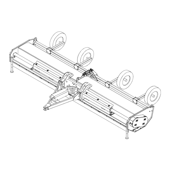
- Page 95 INTRODUCTION The Bush Hog flail shredders are designed to provide maximum shredding of crop material including corn, cotton, milo, rice, wheat and vegetables while leaving the residue evenly distributed across the width of the machine. The BRC flail shredders are available with a 3-Point lift, semi-mount or pull-type hitch in shredding widths of 15’, 18’, 20’...
- Page 96 NOTE: Warranties are honored only if completed “Owner Registration and Warranty” forms are received by Bush Hog within thirty days of delivery of the implement. 3. Record the Model and Serial Numbers on the Warranty page at the front of the Operator’s Manual. Keep this as part of the permanent maintenance file for the implement.
- Page 97 2. If the unit has been subjected to misapplication, abuse, misuse, negligence, fire or other accident. 3. If parts not made or supplied by Bush Hog have been used in connection with the unit, if, in the sole judgment of Bush Hog such use affects its performance, stability or reliability.
- Page 99 ASSEMBLY SECTION Assembly Section 3-1 © 2022 Alamo Group Inc.
- Page 100 ASSEMBLY The BRC Flail Shredders are supplied with a Cat III 3-Point Hitch on semi-mount models or a tongue hitch assembly on pull-type models. SHIPPING STAND REMOVAL Use a 6000 pound capacity hoist. 1. Use overhead hoist to lower machine from shipping position. 2.
- Page 101 ASSEMBLY 3-POINT HITCH ASSEMBLY INSTALLATION (Lift Models Only) 1. Raise hitch into position with hoist. Place narrow section of lower hitch between mounting plates on front of shredder. Fasten with 1-7/16” pins (item 1) to lower holes and lock with snapper pin (item 2).
- Page 102 ASSEMBLY IMPORTANT: Scan this QR Code with your smart phone to link to the ADMA Driveline Safety Manual for more information on the safe use of a driveline during normal operation and maintenance. Or type in your internet browser the following web address: www.algqr.com/dme Ops-0009-MISC str ATTACHING AXLE ASSEMBLIES TO MAIN WHEEL BAR TUBE...
- Page 103 ASSEMBLY ATTACHING OPTIONAL HYDRAULIC CYLINDER (P/N 00725933) Attach clevis end of hydraulic cylinder (Item 1) to mount bracket (Item 2) and attach barrel end to rear mount on center plate. ATTACHING SEMI-MOUNT AXLES 1. Mark desired row spacing with chalk. Keep outer caster wheels as close to the outside as possible. Fasten each caster wheel assembly with clamp plate and 4 bolts and locknuts.
- Page 104 ASSEMBLY LIGHTING INSTALLATION - BRC115/118/120/125 1. Install the light brackets (1 & 2) on the weld studs on the top deck using washers and locknuts (10 & 3). Flat surface should face rearward. Outer light mounting face should be approximately 11-12” from end plate.
- Page 105 ASSEMBLY LIGHTING INSTALLATION - BRC125 END TOW KIT 1. Install the weldment mount (1) on top of end plate using hardware. Fasten light brackets to weldment mount with the flat surface facing rearward for reflector installation. 2. Install the Amber lights on the outer light. Install Red lights to center brackets. 3.
- Page 107 OPERATION SECTION Operation Section 4-1 © 2022 Alamo Group Inc.
- Page 108 BRC115/118/120/125 FLAIL SHREDDER OPERATION INSTRUCTIONS Bush Hog BRC shredders are manufactured with quality material by skilled workers. These shredders are primarily designed to shred crop residue such as cotton stalks, corn, rice straw, milo, rye grass and similar crops. Shredder should be operated at 1000 PTO RPM only, at a ground speed of 2 to 5 m.p.h. Only trained personnel who are familiar with the safety and operating procedures should operate this equipment.
- Page 109 OPERATION 1. STANDARD EQUIPMENT AND SPECIFICATIONS BRC115 BRC118 BRC120 BRC125 Cutting Width 180” 216” 240” 300” Overall Width 204” 240” 264” 324” Cutting Height Range 1” - 18” 1” - 18” 1” - 18” 1” - 18” Cuttershaft Diameter 10-3/4” 10-3/4”...
- Page 110 OPERATION 2. OPERATOR REQUIREMENTS Safe operation of the unit is the responsibility of a qualified operator. A qualified operator has read and understands the implement and tractor Operator’s Manuals and is experienced in implement and tractor operation and all associated safety practices. In addition to the safety messages contained in this manual, safety signs are affixed to the implement and tractor.
- Page 111 OPERATION 3. TRACTOR REQUIREMENTS The tractor used to operate the shredder must have the power, capacity and required equipment to safely operate the shredder at a ground speed between 2 and 5 MPH. Operating the shredder with a tractor that does not meet the following requirements may cause tractor or shredder damage and could be a potential danger to the operator and passersby.
- Page 112 OPERATION 3.2 Tractor Safety Devices If transporting or operating the tractor and implement near a public roadway, the tractor must be equipped with proper warning lighting and a Slow Moving Vehicle (SMV) emblem which are clearly visible from the rear of the unit.
- Page 113 OPERATION 3.5 Drawbar-Pull Type Mower For equipment operating at 1000 RPM, the tractor drawbar must be positioned at a 16” distance from the hitch point to the PTO shaft end for proper operation and minimal wear to the driveline. OPS-R- 0061_E str 3.6 Front End Weight Maintain a minimum of 20% total tractor weight on the tractor front end at all times.
- Page 114 OPERATION 4.1 Boarding the Tractor Use both hands and equipped handrails and steps for support when boarding the tractor. Never use control levers for support when mounting the tractor. Seat yourself in the operator’s seat and secure the seat belt around you.
- Page 115 OPERATION 5. STARTING THE TRACTOR The operator must have a complete understanding of the placement, function, and operational use of all tractor controls before starting the tractor. Review the tractor operator’s manual and consult an authorized dealer for tractor operation instructions if needed. Essential Tractor Controls: •...
- Page 116 OPERATION 6. CONNECTING THE SHREDDER TO THE TRACTOR Use extreme caution when connecting the shredder to the tractor. The shredder should be securely resting on front stands or tongue jack stand and rear gauge wheels. Keep hands and feet from under the shredder ends and clear of pinch points between the tractor hitch arms and shredder pins.
- Page 117 OPERATION 8. DRIVELINE ATTACHMENT The driveline yoke and tractor PTO shaft must be dirt free and greased for attachment. To connect the mower driveline to the tractor PTO output shaft, pull the driveline yoke collar back and align the grooves and splines of the yoke with those of the PTO shaft.
- Page 118 OPERATION 8.1 Driveline Length Check Before operating the Implement, check to make sure the Implement input driveline will not bottom out or become disengaged. Bottoming out occurs when the inner shaft penetrates the outer housing until the assembly becomes solid-it can shorten no more. Bottoming out can cause serious damage to the Tractor PTO by pushing the PTO into the Tractor and through the support bearings or downward onto the PTO shaft, breaking it off.
- Page 119 OPERATION 9. PRE-OPERATION INSPECTION AND SERVICE Before each use, a pre-operation inspection and service of the implement and tractor must be performed. This includes routine maintenance and scheduled lubrication, inspecting that all safety devices are equipped and functional, and performing needed repairs. DO NOT operate the unit if the pre-operation inspection reveals any condition affecting safe operation.
- Page 120 OPERATION 9.1 Tractor Pre-Operation Inspection/Service Refer to the tractor operator’s manual to ensure complete pre-operation inspection scheduled service is performed according to the manufacturer’s recommendations. The following are some of the items that require daily service and inspection: • Tire condition/air pressure •...
- Page 121 OPERATION The operator’s manual and safety signs affixed on the unit contain important instructions on the safe and proper use of the equipment. Maintain these important safety features on the implement in good condition to ensure the information is available to the operator at all times.
- Page 122 OPERATION • Inspect the condition of the drive belts. • Ensure the drive belts shields are in place and in good repair. • Ensure the tractor PTO master shield is in place, lowered and in good condition. OPS-F- 0016_A str •...
- Page 123 OPERATION FLAIL MOWER PRE-OPERATION INSPECTION IMPORTANT: Scan Mower ID# _________________________ this QR Code for an electronic copy of Date:______________________________ this inspection sheet. Make:________________________ Shift:_________________________ Before conducting the inspection, make sure the tractor engine is off, all rotation has stopped and the tractor is in park with the parking brake engaged. Make sure the mower is resting on the ground or securely blocked up and all hydraulic pressure has been relieved.
- Page 124 OPERATION TRACTOR PRE-OPERATION INSPECTION Tractor ID# ____________________ Make:_______________________ Date:________________________ Shaft: _______________________ Before conducting the inspection, make sure the tractor engine is off, all rotation has stopped and the tractor is in park with the parking brake engaged. Make sure the mower is resting on the ground or securely blocked up and all hydraulic pressure has been relieved.
- Page 125 OPERATION 10. DRIVING THE TRACTOR AND IMPLEMENT Safe tractor transport requires the operator possess a thorough knowledge of the model being operated and precautions to take while driving with an attached implement. Ensure the tractor has the capacity to handle the weight of the implement and the tractor operating controls are set for safe transport.
- Page 126 OPERATION 10.1 Starting The Tractor The procedure to start the tractor is model specific. Refer to the tractor operator’s manual for starting procedures for your particular tractor. Consult an authorized dealer if the starting procedure is unclear. Ensure the 3-point control lever is in the lowered position and the PTO is disengaged before starting the tractor.
- Page 127 OPERATION 10.3 Raising the Shredder Using the tractor 3-point hitch control lever, raise the shredder off the ground about 6”, or just high enough to clear any ground obstacles. When raising the shredder, make sure all connection points are securely attached and at least 1” clearance is maintained between the driveline and the deck.
- Page 128 OPERATION 10.5 Turning Procedure Pull-type Units - Pull-type units are fitted with a constant velocity joint at the tractor hitch to allow operating during turns. Do not disengage PTO and end of row. Reduce speed and RPM slightly and proceed with turn. Make wide turns to reduce load on driveline caused by high joint angles.
- Page 129 OPERATION When confronted with an incline or ditch, do not approach from an angle which is perpendicular or straight on as damaged to over collapse of the driveline may occur. When crossing such terrain, the implement should be fully lowered for a lower center of gravity and added stability.
- Page 130 OPERATION 11. OPERATING THE TRACTOR AND IMPLEMENT THE OPERATOR MUST COMPLETELY UNDERSTAND HOW TO OPERATE THE TRACTOR AND IMPLEMENT AND ALL CONTROLS BEFORE ATTEMPTING TO OPERATE. The operator must read and understand the Safety and Operation Sections of the implement and tractor operator’s manuals.
- Page 131 OPERATION 11.1 Foreign Debris Hazards Before mowing, inspect the area to make sure there are no foreign objects that the mower blades could hit or become entangled with. Remove all foreign objects and debris. If objects are too big to remove, mark them clearly and be sure to prevent the mower blades from contacting them.
- Page 132 OPERATION Flail Mowers are capable under adverse conditions of throwing objects for great distances (300 feet or more) and causing serious injury or death. Follow safety messages carefully. STOP MOWING IF PASSERSBY ARE WITHIN 300 FEET UNLESS: - Front and Rear Deflectors, Chain Guards, or Bands are installed and in good, workable condition;...
- Page 133 OPERATION Do not exceed the rated PTO speed for the Implement. Excessive PTO speeds can cause Implement driveline or component failures resulting in serious injury or death. (SG-26) str Do not mow with two machines in the same area except with Cab tractors with the windows closed.
- Page 134 OPERATION 11.5 Shutting Down the Implement To shut down the implement, first bring the tractor to a complete stop. Then slow down the implement by reducing the engine speed before disengaging the PTO. Wait for all motion to stop before proceeding to drive or shut down the tractor.
- Page 135 OPERATION 12. END TOW OPERATION Lift or Semi-Mount Configuration To place the BRC120 or BRC125 in End Tow position, follow this procedure in sequence: Place machine on a level surface on solid ground and shut off tractor engine and engage parking brake before unhitching from machine.
- Page 136 OPERATION 6. Unlatch end tow tongue #1 (Op-320) on left-hand end of machine by unlatching lynch pin. Hold tongue and remove latching pin #2 (Op-320). Pin tongue in lowered position and secure using lynch pin #16 (Op-321). 7. Raise machine using three-point lift of tractor. 8.
- Page 137 OPERATION 13. CONVERTING MACHINE FROM TRANSPORT TO OPERATION 13.1 Lift or Semi-Mount Configuration 1. Chock both wheels of end transport. Lower end tow hitch parking jack #19 (Op-321), disconnect light harness and remove hitch pin to disconnect machine from tractor. 2.
- Page 138 OPERATION 1. Using rear gauge wheel #4, (Op-322) hydraulics, raise machine to maximum height. 2. Unlatch end tow tongue #1, (Op-320) on left-hand end of machine by unlatching lynch pin. Hold tongue and remove latching pin #2, (Op-320). Pin tongue in lowered position and secure using lynch pin #16, (Op- 321).
- Page 139 OPERATION Never stand or allow another person to stand between a running Tractor and the shredder when disconnecting the Implement from the Tractor 3-point hitch. Always shut the Tractor off completely and set the parking brake before attempting to disconnect the shredder pins from the Tractor hitch.
- Page 140 OPERATION Before transporting the tractor and mower, idle the tractor engine, disengage the PTO and wait for all mower moving parts to come to a complete stop. Raise the mower sections and ensure transport locks engage. OPS-F-0021_A str Before transporting the tractor on a public roadway or boarding a trailer for transport, the tractor brake pedals should be locked together.
- Page 141 OPERATION Only tow the Implement behind a properly sized and equipped Tractor which exceeds the weight of the Implement by at least 20%. DO NOT tow the Implement behind a truck or other type of vehicle. Never tow the Implement and another Implement connected in tandem. Never tow the Implement at speeds over 20 MPH.
- Page 142 OPERATION When operating public roads, have consideration for other road users. Pull to the side of the road occasionally to allow all following traffic to pass. Do not exceed the legal speed limit set in your country for agricultural tractors. Always stay alert when transporting the tractor and implement on public roads.
- Page 143 OPERATION Use adequately sized and rated trailers and equipment to transport the tractor and implement. Consult an authorized dealer to determine the proper equipment required. Using adequately sized chains, heavy duty straps, cables and/or binders, securely tie down both the front and rear of the tractor utilizing the proper tie down locations as specified by the tractor manufacturer.
- Page 144 OPERATION 17. TROUBLESHOOTING GUIDE Problem Possible Cause Remedy Excessive Check gearbox bolts. Tighten if loose. Vibrations Check for missing knives on cutter Replace missing knives. shaft. Check to see if knives are free swing- Free knives so they swing.. ing.. Blade broken or bent.
- Page 145 Cutting in sandy conditions. Increase cutting height. Fast Cutting in rocky conditions. Increase cutting height. Soft “will fit” knives. Use genuine Bush Hog knives. Discharging Belt installed improperly. Check belt for correct set up. Bundles or Blades dull. Check blades for sharpness.
- Page 147 MAINTENANCE SECTION Maintenance Section 5-1 © 2022 Alamo Group Inc.
- Page 148 MAINTENANCE HAZARDS WITH MAINTENANCE OF IMPLEMENT AVOID DEATH OR SERIOUS INJURY FROM COMPONENT FAILURE BY KEEPING IMPLEMENT IN GOOD OPERATING CONDITION IN PERFORMING PROPER SERVICE, REPAIRS AND MAINTENANCE. BEFORE PERFORMING SERVICE, REPAIRS AND MAINTENANCE ON THE IMPLEMENT: SECURE EQUIPMENT FOR SERVICE BLOCK OUT POTENTIAL ENERGY HAZARDS;...
- Page 149 These parts are made and tested to Bush Hog specifications. Non-genuine "will fit" parts do not consistently meet these specifications. The use of “will fit” parts may reduce mower performance, void warranties, and present a safety hazard. Use genuine Bush Hog mower parts for economy and safety.
- Page 150 MAINTENANCE To lubricate telescoping section of driveline, disconnect yoke from tractor and compress driveline until both slots on shields are aligned and grease fitting is exposed. Lubricate both u-joints before re-attaching to tractor. Inspect shields to ensure they rotate freely, replace bearings or shield if damaged. *Note: Lubricate roller bearings until lubricant can be seen coming out between roller and bearing housing.
- Page 151 MAINTENANCE DRIVELINES The Drivelines and U-Joints should be inspected each morning before the shredder is started. Cross & bearings are located at each end of driveline. See MntP-FL-0013 & Mnt-FL-0042. The U-Joint and CV Joint on the Driveline undergo extreme forces when the unit is turning. It is important that the U-Joints and CV Joint be greased each day before the unit is started.
- Page 152 MAINTENANCE ROUTINE MAINTENANCE 1. Inspect belt drive for correct tension and remove any debris from inside belt shields. Incorrect tension will result in premature belt failure. Check belt tension after first hour of operation. Mnt-FL-0029_A 2. Inspect for and tighten any loose fasteners. 3.
- Page 153 MAINTENANCE BELT ADJUSTMENT AND REPLACEMENT 1. To adjust belt, loosen both pivot bolts slightly (Item 1), and tighten nut on tension rod (Item 2), which pivots drive assembly forward to tension belt. Correctly tensioned belt should require a maximum of 85 lbs force across entire band to deflect belt 3/8”...
- Page 154 MAINTENANCE 3. To relocate pulleys on drive and cuttershaft, first loosen belt tension and check for shaft movement to ensure they are not loose or have moved. Mark present location of bushing on shaft for future reference. Pulleys are locked to shaft by a tapered hub bushing. Loosen socket head set screw located above key.
- Page 155 MAINTENANCE CUTTERSHAFT BEARING REMOVAL AND INSTALLATION Outer Cuttershaft Bearing Removal 1. Remove belt; disconnect tension rod; loosen adjustment tube pivot points bolts; rotate assembly toward deck; remove belt. 2. Remove lower sheave 3. Disconnect grease line. 4. Remove both set screws from bearing lock collar. (Note: Set screws align with dimples in shaft) Set screws are lock tightened in place.
- Page 156 MAINTENANCE Center Bearing and Cutter Shaft Removal 1. Support and block both cutter shafts at center bearings and support the shaft which is being removed under the drive side. Remove outer bearing as outlined in the Maintenance Section, page 5-8. Remove both bolts fastening center bearing shields and undo external grease line.
- Page 157 MAINTENANCE Top Drive Assembly Servicing 1. To replace outboard bearing, remove belt and top pulley assembly as outlined in Maintenance Section, page 5-6 - 5-8. Clean all burrs from shaft and remove bearing and lock collar as outlined in Maintenance Section, page 5-7.
- Page 158 MAINTENANCE DRIVELINE REPAIR Slide apart both halves of driveline and remove shield by unfastening nylon bearing retainer. Snap ring can be removed by inserting screwdriver under one end. Snap ring may also be accessed through slots on side of shield by bell-end. Always replace nylon bearing kit when installing a new shield. When assembling both portions of driveline, align phase key on end of spline half with double width groove in hub side Step 1: To disassemble the universal joint, remove the four snap rings.
- Page 159 MAINTENANCE Step 3: Clamp vise as shown and tap on yoke to completely remove cup from yoke. Repeat step two and three for opposite cup FIGURE Mnt-FL-0034. Step 4: Place universal cross in vise as shown and tap on yoke to remove cup. Repeat step 3 for final removal. Drive remaining cup out with drift and hammer.
- Page 160 MAINTENANCE Step 6: Seat cup by placing a drift or socket slightly smaller than the cup on the cup and squeeze in vise. Install snap ring and repeat on opposite cup. Repeat steps five and six to install remaining cups in remaining yoke.
- Page 161 MAINTENANCE MAIN CV DRIVELINE SAFETY SHIELD - Pull Type Only To remove the outer CV cone, remove the locking screws from shield cone. Remove cone over yoke. Figure Mnt-R-0141. Remove bearing ring and remove the locking screws from inner shield cone. Figure Mnt-R-0142. Turn inner cone to assembly position and remove half shield.
- Page 162 MAINTENANCE MAIN DRIVELINE & CAT 4 SAFETY SHIELD To remove the main inner driveline shield, remove the locking screws. Align the bearing tabs with the cone pockets. Figure Mnt-R-0026. Remove the half-guard and remove the bearing ring. Figure Mnt-R-0012. Inspect the driveline shield for worn areas or cracks. If the shield has any dents or cracks, replace the shield. While the shields are off, examine the driveline for signs of abnormal wear, bent or twisted shafts or cracks in the shaft or tubes.
- Page 163 MAINTENANCE FLAIL BLADE INSPECTION Inspect the Blades daily for abnormal wear. REPLACE ALL BLADES on the carrier IMMEDIATELY if any blades have: • Become bent or deformed from its original shape, or • Wear inside the blade bolt hole, or •...
- Page 164 MAINTENANCE General Information on Flail Vibration FLAIL MOWERS - INFORMATION BULLETIN NO. 5 Excessive Vibration Vibration is a MONSTER and if allowed to continue unchecked, can cause the complete break-up of a machine in a very short time. A properly operated Flail Mower will produce very little vibration. If vibration does occur, the mower should be stopped and the trouble corrected, as warranty does not cover failures resulting from continued operation after something happens to cause the mower to vibrate excessively.
- Page 165 MAINTENANCE STORING THE BRC115/118/120/125 When storing the unit for an extended period of time, or at the end of a season, lubricate all bearings with enough grease to eliminate any cavities where water condensation may occur and cause damage. Refer to “Lubrication”...
- Page 166 MAINTENANCE BRC115/118/120/125 09/22 Maintenance Section 5-20 © 2022 Alamo Group Inc.
Need help?
Do you have a question about the BRC 115 and is the answer not in the manual?
Questions and answers