Table of Contents
Advertisement
Published 05/16 Revised 08/18
OPERATOR'S MANUAL
This Operator's Manual is an integral part of the safe op-
eration of this machine and must be maintained with the
unit at all times. READ, UNDERSTAND, and FOLLOW the
Safety and Operation Instructions contained in this man-
ual before operating the equipment.
BUSH HOG
2501 Griffin Avenue
Selma, Al. 36703
334-874-2700
www.bushing.com
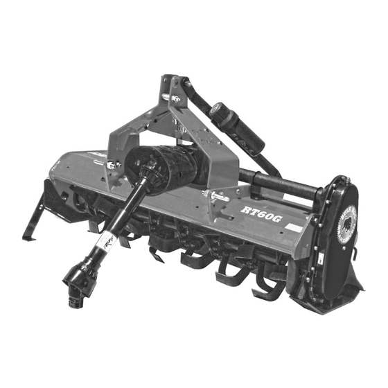
RTG SERIES TILLERS
®
RT60G, RT72G, RT84G
RT60GR, RT72GR, RT84GR
(ROTO HOG)
MODELS
Part No. 50075234
www.bushing.com
Advertisement
Table of Contents


Need help?
Do you have a question about the RT72GR and is the answer not in the manual?
Questions and answers