
Related Manuals for Ecler MIM088SG


Summary of Contents for Ecler MIM088SG
- Page 1 MIMO88SG / 1212SG DIGITAL MATRIXES Installation Digital Matrix USER MANUAL 50-0317-0107 MIMO88SG-1212SG...
- Page 2 INDEX HARDWARE 3-20 ……………………………….……………………………………….………………………..….…..… IMPORTANT REMARK ......................3 IMPORTANT SAFETY INSTRUCTIONS ................3 IMPORTANT NOTE ........................5 INTRODUCTION ........................5 INSTALLATION .......................... 6 5.1. Location, assembly, ventilation ..................... 6 5.2. Connection to an AC outlet and switching on ..............7 5.3.
-
Page 3: Important Remark
IMPORTANT REMARK The lightning flash with arrowhead symbol, within an equilateral triangle, is intended to alert the user to the presence of uninsulated “dangerous voltage” within the product’s enclosure that may be of sufficient magnitude to constitute a risk of electric shock to persons. The exclamation point within an equilateral triangle is intended to alert the user to the presence of important operating and maintenance (servicing) instructions in the literature accompanying the appliance. - Page 4 9. Do not defeat the safety purpose of the polarized or grounding type plug. A polarized plug has two blades with one wider than the other. A grounding type plug has two blades and a third grounding prong. The wide blade or the third prong are provided for your safety.
-
Page 5: Important Note
NEEC AUDIO BARCELONA, S.L. accepts no liability for any damage that may be caused to people, animal or objects due to failure to comply with the warnings above. IMPORTANT NOTE Thank you for choosing our Ecler MIMO88SG / 1212SG Installation Digital Matrix! VERY IMPORTANT It is... -
Page 6: Installation
The MIMO SG programming is done with EclerNet Manager. Please refer to EclerNet Manager Software manual at www.ecler.com for more information. INSTALLATION 5.1. Location, assembly, ventilation MIMO SG series has been especially designed to be installed in a standard 19" rack, taking up 1U. - Page 7 "IN", accepting both line and microphone level signals. Input signal type selection and management are carried out from EclerNet Manager application. Please refer to EclerNet Manager Software manual at www.ecler.com more information. Signal input connectors are 3 position screw terminal block. The wiring is: Hot or direct signal >...
- Page 8 Ground > Terminal ⊥ For UNBALANCED connections, leave the – terminal unconnected.
- Page 9 • Possibility of direct connection (point to point) between a computer and a MIMO SG unit. • Connection to third party other devices. (Crestron, AMX, Vity, Medialon, etc. Registered trademarks of their manufacturers). Protocol used: Ecler TP-NET. the TP-NET protocol manual for more information.
- Page 10 0-10V DC, etc.) and assigned to a MIMO SG function, as for example: • Input, output channel or matrix crosspoint volume remote control by means of a WPaVOL physical knob or an Ecler WP Series’ WPVOL-IR remote control • MUTE or SOLO activation/deactivation by means of a switch or contact closure •...
- Page 11 5.8. Remote control RS-232 Port The built-in RS-232 port in the rear panel allows an external device to communicate with a MIMO SG unit via serial connection. Said connection uses the TP-NET protocol syntax so to enable the external device to obtain the value of any of the parameters of the MIMO SG unit (by "GET"...
-
Page 12: Function List
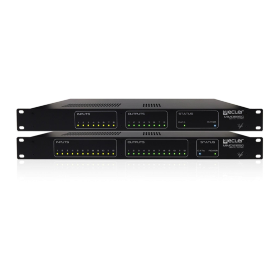
FUNCTION LIST 1. Input signal indicators, INPUTS 2. Output signal indicators, OUTPUTS 3. Data traffic indicator, DATA 4. Power on indicator, POWER 5. Signal output screw terminal, OUT 6. Signal input screw terminal, IN 7. RJ-45 connector, ETHERNET 8. Screw terminals for digital remote control, REMOTE 9. - Page 13 FUNCTION DIAGRAMS 8.1 MIMO88SG...
- Page 14 8.2. MIMO1212SG...
-
Page 15: Technical Characteristics
TECHNICAL CHARACTERISTICS 9.1. MIMO88SG 2x 32/64bit Sampling Rate 48kHz Latency IN to OUT <2.9ms Converters Resolution 24bit AKM Dynamic Range AD:110dB, DA: 115dB Analogue x8 Input/Output Terminal block (Symmetrical) Analogue Input headroom +27dBV = +30dBu Max. output level +18dBV = +21dBu Input sensitivity @ 0dBV out From -50dBV to +10dBV in 0.5dB step... - Page 16 Parametric Eq. Types Bypass / On-Off all channels (4 max per input) Param Eq. Freq: 20Hz-20kHz; Gain: -60/+12 dB; Q: 0.3 to 200 (6 max per input) Low & High Shelf 6/12 dB/oct Low & High Pass 6/12 dB/oct All Pass 1/2 order High &...
- Page 17 Supply Mains 90-264VCA 47-63Hz Power consumption 45VA Miscellaneous Management Connectivity Ethernet Base-Tx 10/100Mb Auto X-Over CAT5 up to 100m Remote Bus Over twisted pairs; up to 1km (see specific specs.) 8, from 0 to 10VDC or TTL level Aux. Power Supply for Remotes & GPI +12VDC, 1.2A.
- Page 18 Output Level (x12) Range: from Off to 0 dB Mute: Yes Solo: Yes Signal Polarity reverse: Yes Metering: VU + clip pre & post fader Output Gain (x12) Range: from 0 to +6 dB Input Delay (x12) from 0 to 1000 ms. Units: sec/ms/m/cm.
- Page 19 Pager (x3) Input: IN1 to IN12 Priorities: 3 (1 max, 3 min) Depth: 0 dB to 80 dB Attack time: from 5 ms. to 2000 ms. Release time: from 50 ms. to 3000 ms. Chime Source: None, Melody 1, Melody 2 Chime Volume: from –12 dB to 0 dB Mechanical Dimensions (WxHxD)
-
Page 20: Block Diagrams
BLOCK DIAGRAMS 10.1. MIMO88SG... - Page 21 10.2. MIMO1212SG...
- Page 22 TP-NET PROTOCOL SOFTWARE Third-Party NET USER MANUAL...
- Page 23 • Stop bits: 1 • Flow control: None In case the Ecler device has an Euroblock connector for the RS-232 interface, the serial cable wiring, from the device’s connector to a standard DB9 serial interface connector, must be the following: The protocol is simple and direct, making it easy to read, write and modify the generated code.
- Page 24 The available messages are built with one or more fields separated with blank spaces ( = blank space): <TYPE> [PARAM1] [PARAM2] [PARAM3] [PARAM4][LF] The first field (TYPE) defines the message type and then, the required parameters for it (each kind of message requires a given number of parameters). The field TYPE can have these values:...
- Page 25 messages don’t have an automatic acknowledgement with a DATA message sent from the EclerNet device after it has processed the command. The client must update the values itself and must send the needed message if it requires confirmation from the device. NOTES: •...
- Page 26 MIMO88SG / MIMO1212SG (SINGLE) DIGITAL MATRIX IMPORTANT NOTE: The communication must be started with the client sending the first message SYSTEM CONNECT to the EclerNet device. Otherwise, the commands from the client to the EclerNet device will be ignored. See TP-NET PROTOCOL INTRODUCTION chapter for additional information.
- Page 27 XMUTE <Input Channel> <Output Gets the current MUTE status of a Matrix Point Channel> <Input Channel> Gets the VU-meter value of an Input Channel <Output Gets the VU-meter value of an Output Channel Channel> <Input> Gets the current value of a General Purpose Input <Output>...
- Page 28 TYPE PARAM1 PARAM2 PARAM3 PARAM4 DESCRIPTION PRESET <Preset Number> Sets the current PRESET ILEVEL <Input Channel> <Level> Sets the current LEVEL of an Input Channel OLEVEL <Output Channel> <Level> Sets the current LEVEL of an Output Channel XLEVEL <Input Channel> <Output <Level>...
- Page 29 XLEVEL <Input Channel> <Output <Value> Decreases the current LEVEL of a Matrix point by Channel> Value (Value can range from ±1 to ±100) SUBSCRIBE Subscribes to all VU-meters <Input Channel> Subscribes to an Input Channel VU-meter <Output Channel> Subscribes to an Output Channel VU-meter UNSUBSCRIBE Unsubscribe to all VU-meters <Input Channel>...
- Page 30 TYPE PARAM1 PARAM2 PARAM3 PARAM4 DESCRIPTION DATA PRESET <Preset Number> Shows the current PRESET ILEVEL <Input Channel> <Level> Shows the current LEVEL of an Input Channel OLEVEL <Output Channel> <Level> Shows the current LEVEL of an Output Channel XLEVEL <Input Channel> <Output Channel>...
- Page 31 MIMO88SG CONFERENCE DIGITAL MATRIX IMPORTANT NOTE: The communication must be started with the client sending the first message SYSTEM CONNECT to the EclerNet device. Otherwise, the commands from the client to the EclerNet device will be ignored. See TP-NET PROTOCOL INTRODUCTION chapter for additional information.
- Page 32 ERROR CODES FOR ECLERNET DEVICES 14.1. COMMON ERROR CODES (to all EclerNet - TP-NET compatible devices) ERROR ID DESCRIPTION TPNET_ERROR_NONE = 0, TPNET_ERROR_INVALID_FIELD_TYPE, TPNET_ERROR_INVALID_FIELD_PARAM1, TPNET_ERROR_INVALID_FIELD_PARAM2, TPNET_ERROR_INVALID_FIELD_PARAM3, TPNET_ERROR_INVALID_FIELD_PARAM4, 14.2 MIMO88SG, MIMO1212SG, MIMO88SG CONFERENCE & MIMO1212SG CONFERENCE SERIES SPECIFIC ERROR CODES ERROR ID DESCRIPTION UDP_ERROR_TIMEOUT_PONG, UDP_ERROR_CONNECT_WHILE_CONNECTED,...
- Page 33 NEEC AUDIO BARCELONA S.L. reserves the right to make changes or improvements in the design or manufacturing that may affect these product specifications. For technical queries contact your supplier, distributor or complete the contact form on our website, Support / Technical requests. Motors, 166‐168 08038 Barcelona ‐ Spain ‐ (+34) 932238403 | information@ecler.com www.ecler.com...
Need help?
Do you have a question about the MIM088SG and is the answer not in the manual?
Questions and answers