
Related Manuals for Vent-Axia HR4


Summary of Contents for Vent-Axia HR4
- Page 1 Please leave these instructions with the user Semi-Remote Wall Mounted Heat Recovery Unit With Spigot Connections & Integral Fans Installation and Servicing Instructions...
-
Page 3: Table Of Contents
Contents Section Page Introduction Site Requirements Installation Electrical Maintenance & Accessories Notes... -
Page 4: Introduction
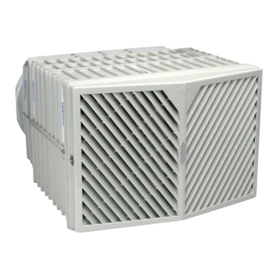
1.0 Introduction Description 1. The Vent-Axia HR4 unit is self contained, with integral extract and supply fans to provide balanced ventilation and heat recovery via supply diffusers and extraction grilles. The unit is designed for installation in external walls and should be fitted to provide a 3° slope to outside to provide condensate drainage. -
Page 5: Site Requirements
3° 2. The unit is suitable for use at a maximum ambient temperature of 45°C. 3. The HR4 unit should be placed as high as 3° Angle for Fig. 4 possible, in an exterior wall to a minimum condensate drainage distance of 125mm (5”) from the ceiling. -
Page 6: Installation
3.0 Installation Initial Preparation 1. Working from the inside, mark out the position of the hole to be cut. This should be 610mm (24”) x 380mm (15”) (Fig. 8). 380mm (15”) 2. Mark the centre of the cut-out by drawing diagonal lines from the four corners. - Page 7 3.0 Installation Installing the Appliance 1. Carefully line up the unit into the wall Typical Installation External aperture, ensuring that the wire is fed into the Wall unit through the grommet as shown. 2. Position the unit in the wall aperture, ensuring that there is a 3°...
-
Page 8: Electrical
Terminal Block experienced from activity in a swimming pool. The unit 1.0-1.5mm Cable Single HR4 unit wiring would automatically return to normal speed 1 or 2 once the VCON 33S speed controller humidity levels have been reduced. -
Page 9: Maintenance & Accessories
5.0 Maintenance & Accessories Cleaning the Unit 1. The heat exchanger will require occasional cleaning to remove build up of deposits. 2. The cassette is easily extracted by unscrewing the 4 x M6 cover bolts (Fig. 11). Cover Bolts 3. Debris can be removed and cleaned by using a vacuum cleaner, or by washing in luke warm soapy water. -
Page 10: Notes
6.0 Notes... - Page 12 370695B - 0904 A Division of Vent-Axia Limited. Fleming Way, Crawley, West Sussex RH10 9YX Technical support:- 01293 526062 Fax:- 01293 539209 Internet Site at:- www.vent-axia.com...
Need help?
Do you have a question about the HR4 and is the answer not in the manual?
Questions and answers